Some months ago STMicroelectronics gave out free STM32F4 Discovery boards. I was one of those few lucky (actually almost everyone got it) to get a free board. Last semester I used the board for my class project (Real Time and Embedded Operating Systems) along with Keil. I also have a netduino board which is my favourite of all dev boards I have because I can use Visual Studio and C#. I know the limitations of managed code running on metal because of the CLR’s overhead. But my applications are not real-time signal processing. Last week I accidentally bumped into a site http://netmf4stm32.codeplex.com/ and was pleasantly surprised that .NET MicroFramework was ported (or in the process) for STM32 boards. So why not try it? Well, also this time I made sure I document the whole process of doing this along with screenshots. The source of this work is taken from the post http://netmf4stm32.codeplex.com/discussions/400293. Thanks LouisCPro and the members of http://netmf4stm32.codeplex.com/team/view. The whole thing took me less than 2 hours (including installing Visual C# Express 2010). Here we go…….
Make sure you have the following
1) STM32F4 Discovery board
2) USB Micro and USB Mini cable (Yup, you need both)
3) STM32 ST-LINK Utility (to drop the bootloader to the discovery board. It also has the driver) http://www.st.com/web/en/catalog/tools/PF258168
4) Download stm32f4discovery.zip and STM32_WinUSB_drivers_(for_evaluation_purposes_only).zip from http://netmf4stm32.codeplex.com/
5) Visual C# Express or Visual Studio 2010 (not 2012 right now) http://www.microsoft.com/visualstudio/eng/downloads#d-2010-express
6) .NET MicroFramework SDK (this is for 4.2) http://netmf.codeplex.com/releases/view/91594
7) An LED (To test the hello blinky)
After you have installed everything (Yes, please install everything). Now connect the USB Micro cable
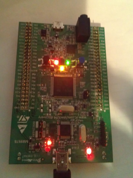
(I had a different firmware in there, that’s why its all lite up)
Once you plugged in the board it will start looking for driver. If you have installed the STM32 STLink utility, then it will automatically install the driver. If you missed it, please install it. Run the STM32 Utility (usually is located in C:Program Files (x86)STMicroelectronicsSTM32 ST-LINK UtilityST-LINK UtilitySTM32 ST-LINK Utility.exe for default installation).
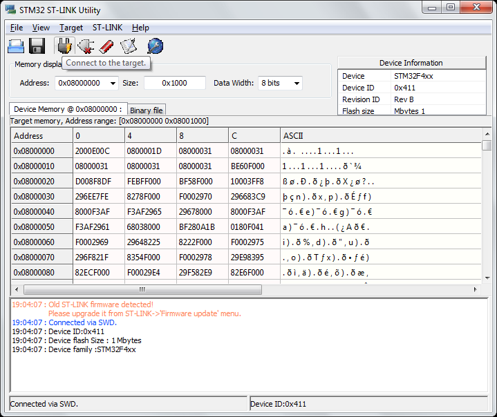
After you are connected to the utility, erase everything on the STM32F4 (don’t worry, you won’t brick anything) by following the screenshots below (yes delete both Chip and Sector, one after the other)
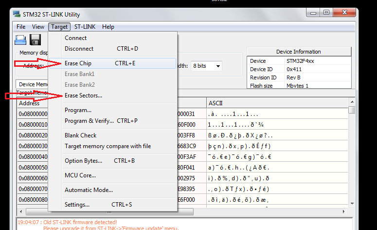
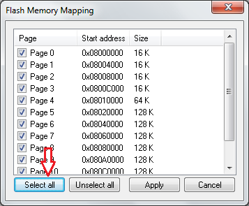
Now the chip is clean. Remember point 4 on the top of the page where you were asked to download 2 zip files? extract them and have them handy (we will be using it). In the stm32f4discovery.zip you will see 3 files: Tinybooter.hex, ER_Flash.hex and ER_Config.hex.
Using the ST Link utility download Tinybooter.hex into the chip (Screenshot below)
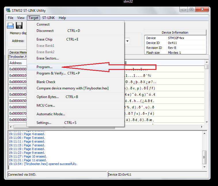
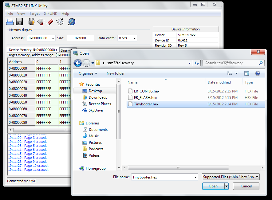
After you have successfully downloaded press reset button on the board (or just remove the usb and plug it in again). After you have uploaded the Tinybooter.hex, the Mini USB will act only as a power supply for our project. After you have reset your board now plug-in the USB Micro USB (the other USB). I used my phone charger cable. Most of the smart phone cables should be Micro USB.
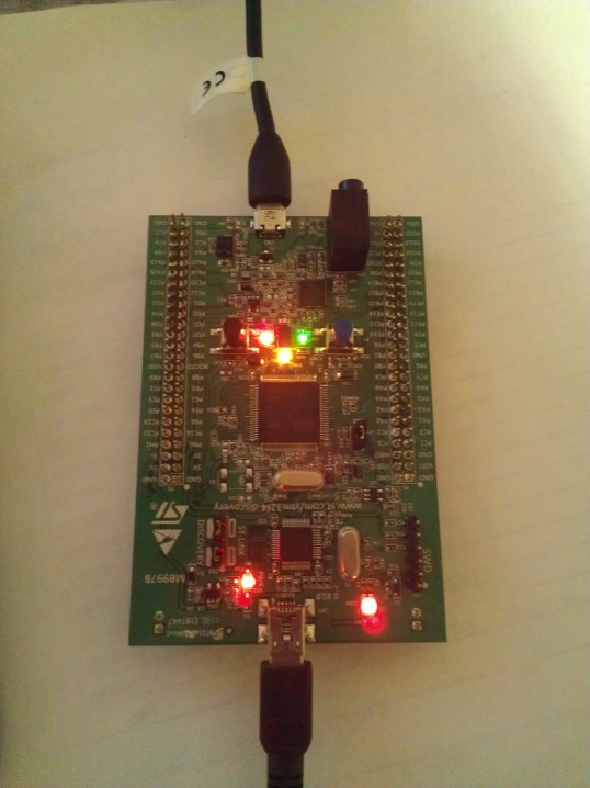
Once you connected the Micro USB, windows will start searching for driver and will fail. Now we got to install the driver we downloaded from the other zip file named “STM32_WinUSB_drivers_(for_evaluation_purposes_only).zip“. Follow the screen shots give below if you don’t know how.
Go to Devices and Printers from your Start menu and then
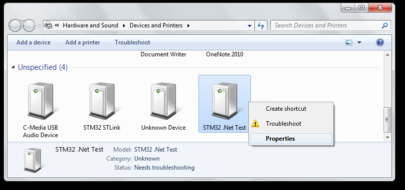
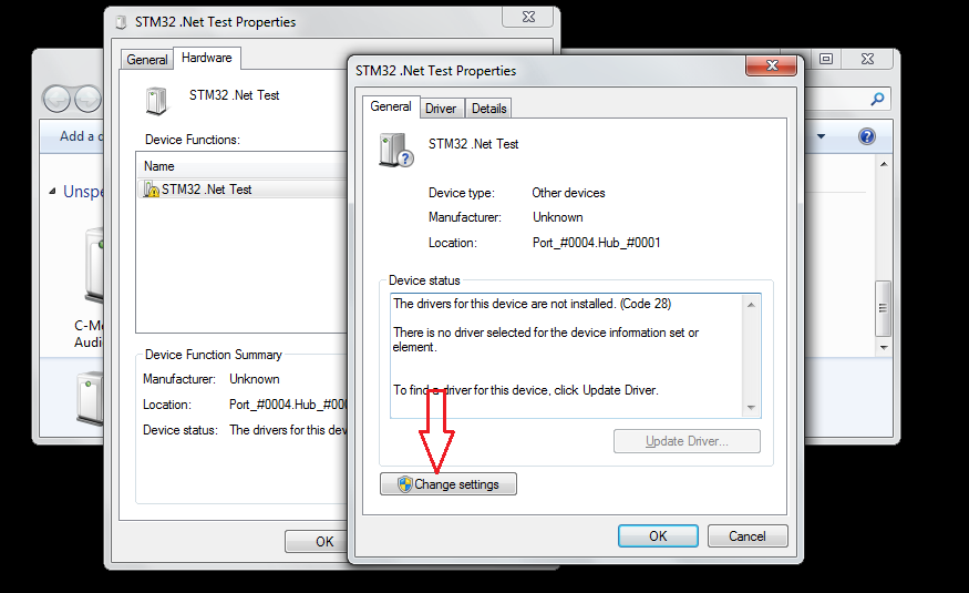
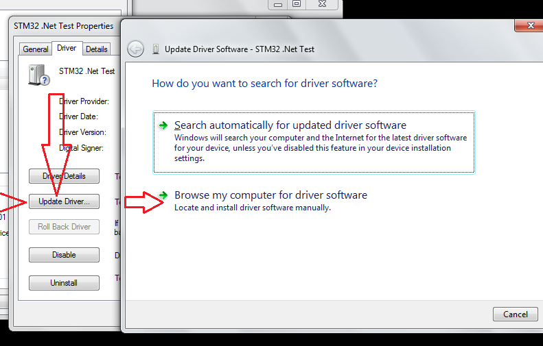
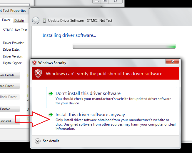
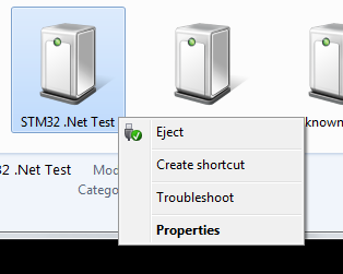
Now the MFDeploy should be able to see this board. MFDeploy is MicroFramework Deployer (duh). Using this software we’ll install the CLR on which our .net code will run. Alright, now launch MFDeploy.exe (you should be able to find it in C:Program Files (x86)Microsoft .NET Micro Frameworkv4.2ToolsMFDeploy.exe) which you should have got when you installed the SDK. To make sure MFDeploy can see the board do as shown below.
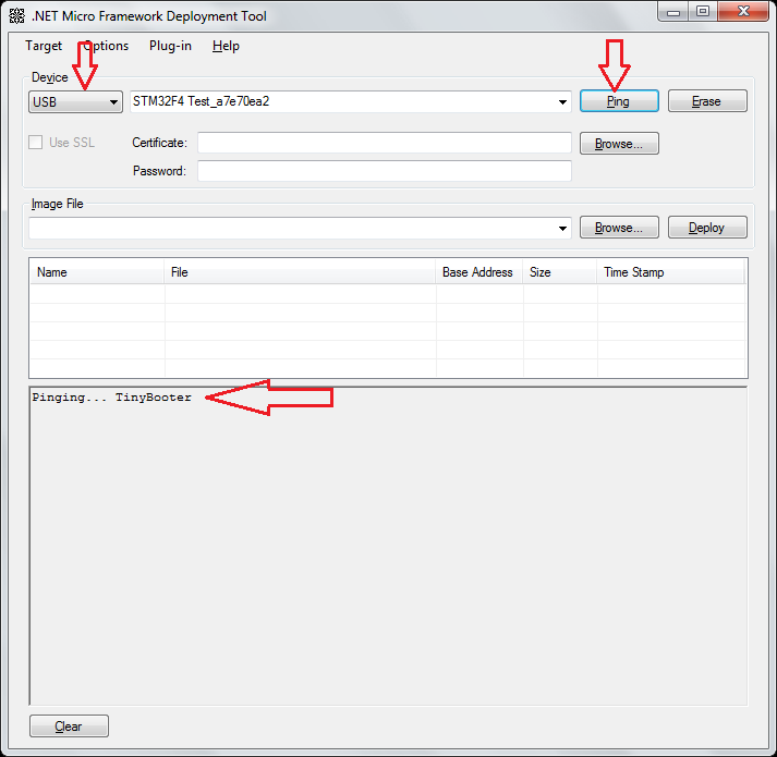
If you see the Ping the everything is good till this point. Now download the other 2 .hex (ER_Config.hex and ER_Flash.hex) files extracted from stm32f4discovery.zip file to the board using the MFDeploy as shown below
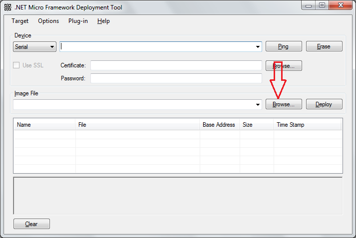
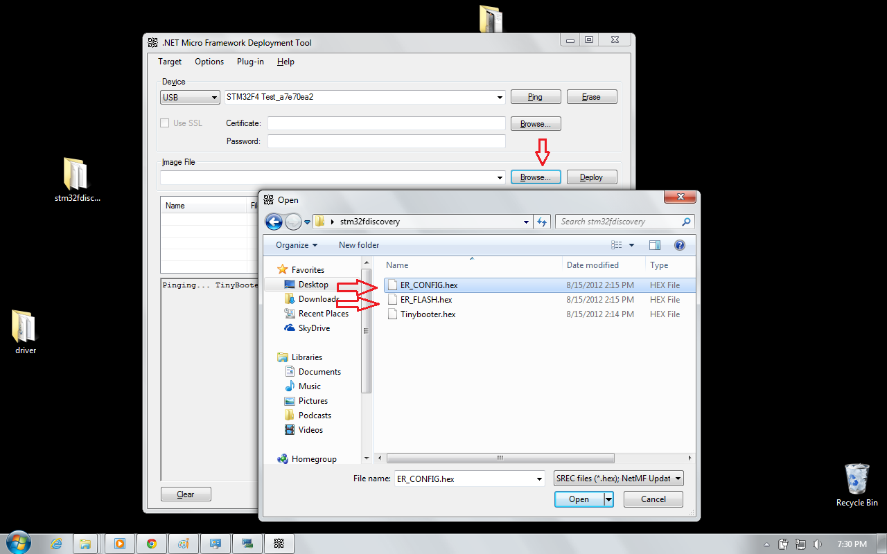
Reset the board.
Congratulations! You got a .NET Microframework board!
Now we need to test our board. So open your Visual C# Express/ Visual Studio. I am sure you should have installed the Microframework SDK. Select the project type as given below
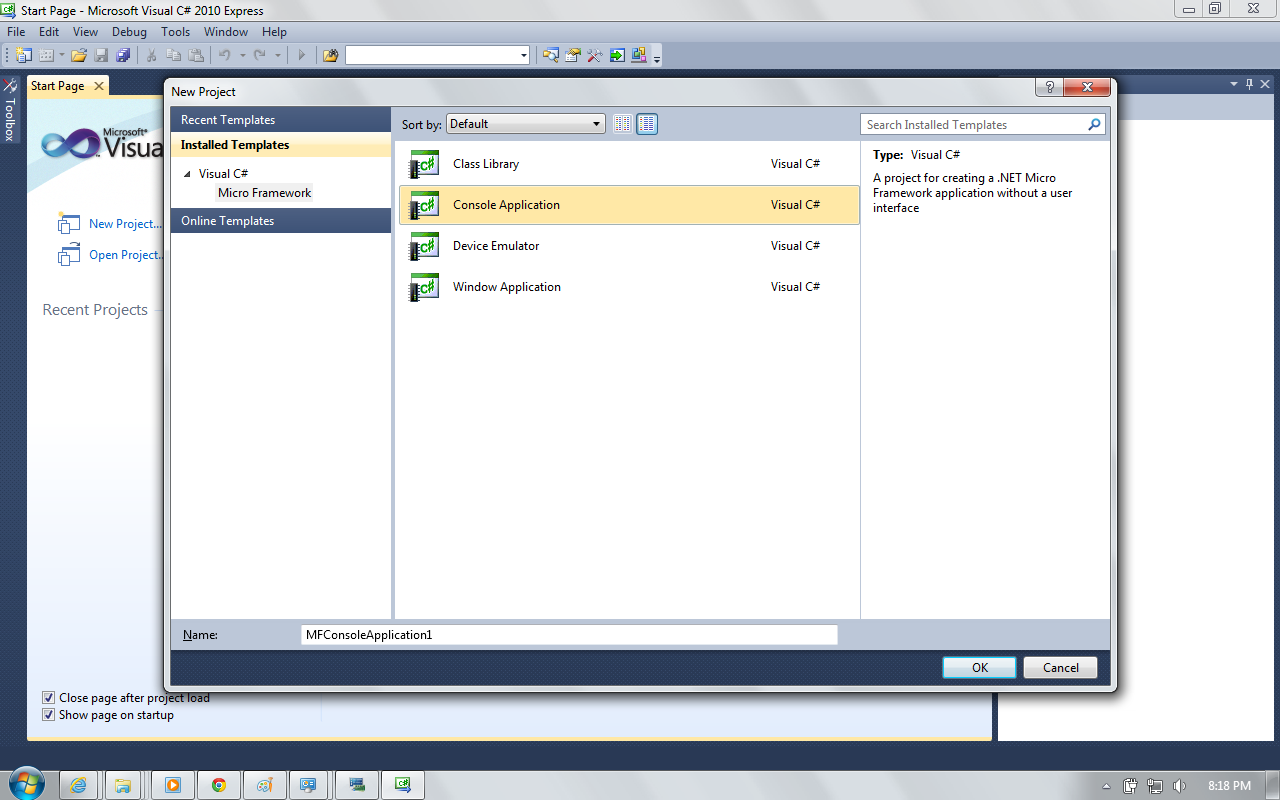
Now we need to change the properties, so that the Visual Express/Studio will deploy to the hardware. So change the project properties as shown below
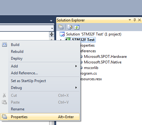
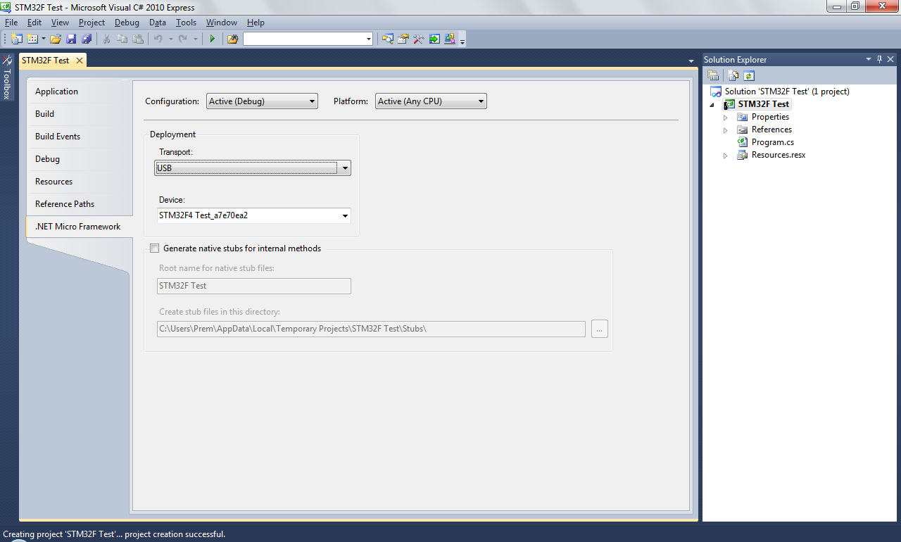
Now we need to add hardware class so that we can run a program to blink and LED.
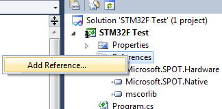

Here is my test code
using System;
using System.Threading;
using Microsoft.SPOT;
using Microsoft.SPOT.Hardware;

namespace STM32F_Test
{
    public class Program
    {
        public static void Main()
        {
            OutputPort led = new OutputPort(Cpu.Pin.GPIO_Pin1, false); //PA1 on discovery board

            while (true)
            {
                led.Write(true);
                Thread.Sleep(500);
                led.Write(false);
                Thread.Sleep(500);
            }
        }

    }
}
Oh, to know the pin map follow this file “C:MicroFrameworkPK_v4_2DeviceCodeTargetsNativeSTM32ManagedCodeHardwareCPU.cs” which you will find if you installed the porting kit (not included in the list above)
Here is the video
[youtube=http://www.youtube.com/watch?v=waKveMdQq1o]
It’s great to run .net on the ST dev board, as those are dirt cheap, but there already is a STM32 board running .NET MF: the Netduino Go…
Very Nice…
Does this work on STM32F3 ? (with less memory)
I doubt it. CLR requires at least 64KBytes of RAM. F3 series according to ST’s site says “The STM32 F3 series includes devices with 64 to 256 Kbytes of on-chip Flash memory, up to 48 Kbytes of SRAM” which i don’t think is sufficient.
If you use this code you dont need an external LED. You have to add c:MicroFrameworkPK_v4_2DeviceCodeTargetsNativeSTM32ManagedCodeHardwareCPU.cs to project.
using System;
using System.Threading;
using Microsoft.SPOT;
using Microsoft.SPOT.Hardware;
namespace STM32F_Test
{
public class Program
{
public static void Main()
{
OutputPort led = new OutputPort(Microsoft.SPOT.Hardware.STM32.Pins.GPIO_PIN_D_12, false); //PA1 on discovery board
while (true)
{
led.Write(true);
Thread.Sleep(500);
led.Write(false);
Thread.Sleep(500);
Debug.Print(“Test”);
}
}
}
}
Yes and it comes with installation of Porting Kit 4.2 which was not listed in the list of required items. But yes, you can use it.
Is it possible to use System.IO.Ports.Serial on the discovery board, and when how?
Here is a bunch of tutorial that might help you http://www.ghielectronics.com/support/dotnet-micro-framework
Simply try this :
Serial1 = new SerialPort(SerialPorts.COM2, (int)BaudRates.Baud9600, Parity.None, 8, StopBits.One);
And connect to the related pins on the STM32F4DISCOVERY :
rxPin = Pins.GPIO_PIN_A_3;
txPin = Pins.GPIO_PIN_A_2;
ctsPin = Pins.GPIO_PIN_A_0;
rtsPin = Pins.GPIO_PIN_A_1;
Hi there! Nice write-up. I’ve been trying (with little success) to follow your procedure.
I’ve hit a stumbling block when deploying the ER_FLASH hex file, using MFDeploy. I am able to do everything up to this point, including load the ER_CONFIG file successfully, but I can’t get ER_FLASH to deploy. The process starts, and then fails when attempting to write (may have been erase, I’m not at work to check currently) the first memory location for the ER_FLASH file.
Can you offer any thoughts as to why this may be? I have the GHI gadgeteer system installed, but that shouldn’t be affecting this separate process, right? Maybe I somehow have a different version of the ER_FLASH hex file?
I’d be very grateful for any suggestions from anyone!
Cheers,
Tom
Are you working with STM32F4 Discovery board? Make sure you have nothing connected to the discovery board (all pins should be free – nothing should be connected to the pins.also make sure when you erase the chip you also did erase all the sectors (as given in the screenshot. Try writing ER_FLASH first. Also make sure you downloaded the right files. The gadgeteer will not affect this.
The board is stock, fresh from the blister pack. Nothing is connected to any pins. I have followed your procedure to the letter, and tried several times, including varying the order of ER_FLASH & ER_CONFIG, with the same error every time. The files were downloaded from the link you provided… I will try with a colleagues board tomorrow, but given that the error exists for only ER_CONFIG, I suspect that file, rather than hardware. I will re-download the files and try that too.
Cheers,
Tom
Hi Again,
I’m still having trouble with this! I’ve checked all the previously mentioned points, and the only difference that I can find in my method / setup is that I have a Rev Z MCU, as opposed to your Rev B. Is this likely to make any difference?
Cheers,
Tom
Hello!
I’ve finally found where my process was falling down. In MFDeploy, I was selecting and deploying the ER_FLASH and ER_CONFIG one by one. This always resulted in failiure.
If both files are selected in the browse dialog, and deployed together, the procedure works.
With that sorted, I’m now up and running with the serial ports and LED’s, with my sights set on the rest of it before too long!
Thanks again for the writeup,
Tom
Thanks for this tutorial
yes, there are already plenty of dev boards with netmf but if someone consider build own system based on netmf then there is solution to build own board. I’ve already designed my own board with additional 8MB flash.
I believe that it is best to write extra on this matter STM32F4 Discovery Board running .NET MicroFramework Singular Engineer. It won’t be a taboo subject but generally individuals are not sufficient to speak on such topics.
I have to thank you for the efforts you have put in writing this website.
I’m hoping to see the same high-grade blog posts by you later on as well. In truth, your creative writing abilities has motivated me to get my own, personal blog now 😉
Hello, really good tutorial 😉 Led blinking in 15 minutes after reading this.
But i have problem, can i connect USB Keyboard (HID) to this device? I dont know how to do it with .NET, what i need to include and how to connect debug+keyboard both?
Thanks for reply Roman
Dear Roman,
I never tried a USB keyboard or mouse before with .netMF. Don’t want to give you a wrong direction with thinks i don’t know. But if you find something i’ll be happy to see a walk-through of it.
In case you are not offering your services in multiple cities then
probably there will be no benefit of posting classifieds in that city however this doesn’t
mean that you cannot post your advertisements or the classifieds in that city but what
you have to keep in mind is to mention that the service is available in selected or in one city only.
In these times where the cost of living increases and wages are not,
it seems that charity shops will remain popular not only
because of the money they raise for good causes, but also because no
other Store offers quite the same mix of exclusivity and in any major agreements in the same
way that a charity shop can. If you don’t know then don’t
hesitate to ask the salesman: “Is this absolutely everything
I’m going to need.
I’m really impressed with your writing skills as well as with the layout on your blog. Is this a paid theme or did you modify it yourself? Either way keep up the excellent quality writing, it’s rare to see a nice blog like this one nowadays.
Sorry for a very late reply. No – this is not a payed job. Its just something I want to try writing a blog.
I think these are just generic spam comments, trying to place links to their websites for SEO (search-engine-optimizing). You’d better delete them than reply…
PS. I like your article!
There’s certainly a great deal to learn about this topic. I love all of the points you made.
Thanks, I run it
Hello colleagues, how is all, and what you desire to say about this post,
in my view its truly remarkable designed for me.
Pretty nice post. I just stumbled upon your blog and wished
to say that I have truly enjoyed surfing around your blog posts.
After all I will be subscribing to your feed and I hope you write
again soon!
Sorry to be a bit picky – I like this and I’m going to try it – but the first picture shows a USB Mini connection, not a USB micro connection – which is correct?
Thanks for an interesting project
The mini usb will be used up till you burn the tinybooter.hex. After that the mini usb will act just as a power supply for the board. The micro usb will used for the other 2 hex file and MFDeploy step.
Hi,
I appreciate your article a lot. However, I have serious problem forcing my stm32f4discovery board to work. I successfully uploaded tinybooter.hex and after reset, the system (win 7 x64) detected STM32 .Net Test device. I chose usb drivers to install then and everything appeared to be fine. But MFDeploy cannot see any device connected to USB. I have rev Z board. There is nothing connected to the board except two usb cables and I ereased my chip using ST-LINK utility. Any ideas? I really wanted to evaluate .Net framework on my ARM uC. Thanks in advance.
Hi L0nger (and everyone)
I’m having the same problem with the WinUSB drivers. I have had the whole thing up and running, and I’ve deployed several apps to the STM board, but then it all stops and Windows either doesn’t recognise STM.Test or it recognises it and then says there is an error. Endless connecting and disconnecting and erasing and reflashing sometimes fixes it, but often doesn’t. Under these conditions MFDepoy cannot see it.
Its a great pity, because when it does work, its fantastic! I’ve posted a query to Cuno Pfister who seems to be the originator of some of this – especially the drivers – and am hoping for some advice. The WinUSB drivers do carry a warning though, so we may have to accept this until they become more stable. Trouble is, I really want to get going.
On a slightly different topic, when it did work, I managed to get all the GPIO pins toggling – even the four LEDs on the STM board, but I’m stuck as to how to find the PWM, I2C, UARTs etc. (and which is which). I’m sure its in the documentation somewhere, but I’m not all that familiar with this stuff, so I do not know where to look.
Anyone help?
Hi,
thanks for your reply. I will greatly appreciate if you post some information about the driver when you contact the author.
It seems though that it’s the matter of driver, not the board. I really doubt that boards rev A,B,Z differ much from each other.
After downloading the tinybooter.hex and restarting the board the mini usb is used as a mere power supply. The micro usb connected is what the microframework will be dealing with.
Yep, you’re right. I tried connecting and disconnecting, erasing and flashing many times. Nothing helped. The driver installs well, but MFDeploy cannot see the device.
Hello, thanks for the article.
I have done program the boot loader, MS deploy detects my STM32 Discov, All is ok. But when i compile (USB in property setting as you given) nothing happen, when i press debug button it will be disabled, hope the debugging is going on, but even after 2,3 minutes it is the same. Can we see program loading?
What will happen when we press debug button?
Regards
Vishal
I dont have this file and directory
c:MicroFrameworkPK_v4_2DeviceCodeTargetsNativeSTM32ManagedCodeHardwareCPU.cs
you need to install the .net microframework
Update on USB driver problems – solved!
I posted on 31st Jan about problems I was having getting the USB link to work reliably. There seemed to be a caveat about the USB drivers (‘for evaluation only’) and I had assumed that was the problem and laid all the blame on that. I corresponded briefly with Cuno Pfister and he explained that there was no problem with the drivers, only that a licensing issue required them to be released as ‘for evaluation only’. After LOTS of installing and re-installing I finally found the cause of the problem – my ‘5V USB supply’ was actually running at about 4.5V, and this caused the intermittent and sporadic failure of the system. Since I started using an independent 5V supply ALL the problems have gone away – if you are having problems, check your USB supply voltage.
I’m still looking for a definitive list of pin numbers/device numbers for all the interfaces. I have got the 4 LEDs going (at 100kHz), plus UART and PWM. I’d like to explore I2C but don’t know where to start looking – even when I find the pin numbers, its not always straightforward to link up with the .NET/c# references to these I/O systems. Is there a definitive list anywhere? Anyone fancy drawing one up, or starting to contribute to the development of one?
This is a fantastic piece of kit which exploits the rich development environment of .NET/c#/VS2010, although I have yet to push the boundaries of performance, given the limitations of .NET.
hi Philip,
This should help you https://netmf4stm32.codeplex.com/SourceControl/changeset/view/a73f4371d473#MicroFrameworkPK_v4_2/DeviceCode/Targets/Native/STM32F4/STM32F4_template_selector.h
Brilliant – thanks a lot. I had that file (along with several hundred others) – just didn’t know where to look.
Thanks again!
Yes, You give me a light. I have the same problem. After I use a stand along 5V USB power, Then the MFDepoy.exe can see my Borard. Thanks!
Hello, really good & informative tutorial. I have successfully done this. But there is a problem now stlink is not communicating with stm32 board it gives internal command error. what should I do ? how I can retain original configuration of stm32 baord ?
Use Mini USB connector (not the Micro). Also erase the chip and sectors completely and you are good to go.
To get the firmware that board already had when you received, you need to download it form the ST site. I forgot the location, but it was along with their peripheral library. Download it and compile it with Keil or other compilers (you get free versions with code limit – don’t worry, you won’t exceed).
driver link is dead. dev community needs this.
All links seems to be working properly. which one is not working?
> driver link is dead. dev community needs this.
i need it too.
All links seems to be working properly. which one is not working?
Hi All,
I have just been using some code (at http://www.ghielectronics.com/community/codeshare/entry/436 hope this is OK to post this) to communicate with the LIS302DL accelerometer via the SPI interface. The code originally ran on a ‘Cerberus’ board so some pins have to be jumpered to get access to the LIS302DL pins on the Discovery board. It worked (or seemed to) until I noticed I only ever got ‘odd’ values (no even ones) of acceleration. Anyone else had any luck with the LIS302DL?
@Philip
More of a ghi community question.
Hi Again,
My mistake – the code *will* run on the Discovery – I had misunderstood the purpose, thinking it was modified *from* the Cerberus. You don’t need to jumper it, and both even and odd values appear. It is quite useful for the Discovery because it illustrates how to use SPI *and* the LIS302DL. Just make sure you use PE3 for CS (the STM documentation wrongly states PE2)
[Please delete both posts if you think fit]
Is there netmf library for the LCD module for discovery board or something that can be used?
Which LCD controller are we talking about? You might be able to get your answers here http://netmf4stm32.codeplex.com/. This whole writeup is just to prepare a board ready for .net.
Excellent !!
Just followed the description, and have the led blinking now!
Took me half an hour to install and run .
Thanks for your well explained tutorial.
Best regards from France.
Olivier
I’m glad it helped you Oliver!
Thanks!
Worked like a champ!!!!! Followed the tutorial, and sent from there. Used it with VS2012 and MF4.3.
*Notes*:
I had to change to release mode and set the framework to 4.2 to get it to work so far! Could have have been something I did, dunno yet, but got it to work without really trying too hard.
It took about 20 mins start to finish. I had downloaded all of the files etc… prior to install.
Now its time to start in on the C# based robot executive…
Thanks – Great writeup!!
Good to hear that it helped you Scott. Good luck with your robot executive and keep me posted! like to hear what .netmf can do!
I can not install the STM32_WinUSB_drivers_(for_evaluation_purposes_only). Can somebody help me how I should install this? I have Win7 32 bit operation system. thx
@Keno
Actually I don’t have STM32 .NET TEST in the device and printers
Connect the Micro USB cable and you’ll see the board listed.
Dear Singular
I made all the steps and it runs ok. thank You very very much !
I have a netduino plus 2 board, and I would like to know the following: if I replicate the sdcard and ethernet connections to my F4discovery, using the same pins, will the software that runs on arduino run at Discovery ?
Thank You
Dear Vidal,
You might have to look into gadgeteer’s website for that info and you can ask your question here and netduino forum.
No, arduino will not run on discovery.
@singularengineer
Sorry
I wrote that wrong. The correct is:
If I replicate the sdcard and ethernet connections to my F4discovery, using the same pins of N+2, will the software that runs on NETDUINO PLUS 2 run at Discovery ?
the idea is to use the less expensive f4 board connected at net.
Thank You.
Connect PA9 to 5V on board to power with usb micro only
@Vidal
Sometimes yes.. netduino is nothing but a bunch of additional libraries to adapt the stm32f4 libraries to the netduino boards. some codes will work on both and some codes will need you to modify the pin descriptors in the library. I’d not recommend using netduino libs in your stm32discovery because your’re gonna have several issues to modify. but you if you want to take advantage of the available code examples for netduino, study them, and look deep into the netduino libraries to try to replicate them to your stm32. I’m personally disappointed with netduino, it seems a bit obsolete and not easy to reuse code
@willianma
write me at vp @ vidal com br
Hi, singularengi,
First of all thanks very much for the very detailed write up. I was able to load NTMF firmware onto F4-Discovery board and some of my homebrew boards too.
My question is: is there any way to deploy tinybooter + NTMF firmware + user code into a bare bone STM32F4 in one shot? If so, that can save much time during production. My experience with MSP430 tells me this can be done, but I am not quire sure how to exactly do it on STM32F4.
If you may, please educate me on this.
Thanks again.
In one shot, not possible. because without the tinybooter running you wont be able to put in the CLR. Without which you cant run the user application. So there is a dependency from ground up that has to be satisfied.
@singularengineer
Thanks for your promptly reply. I understood the dependency. From the perspective of Flash memory, tinybooter, tinyclr and user code are simply bytes stored in different addresses. So my question is, after I load these three elements onto one MCU unit, can I do a memory dump, then load the memory image onto other units? I tried this once on my board, it didn’t work. I am not quite sure what I missed.
Btw, GHIelectronics offer a FEZ_configure tool. This tool greatly facilitate deployment. Still again, tinybooter needs to loaded first through dfu.
I understand NTMF targets the small volume sector. But even for a production run of several hundred units, the deployment can be quite laborious.
Its a valid point. May be you should ask the GHI forum because I have no answer. But if you find one, please let me know. Will be glad to know why it is not possible (if its not).
GUS, the guy who founded GHIelectronics, confirmed my point on their forum. But I haven’t figure out how to do this. When I do, I’ll leave comment here.
If you want use interrupt on the discovery board
It should work:
using System;
using System.Threading;
using Microsoft.SPOT;
using Microsoft.SPOT.IO;
using Microsoft.SPOT.Hardware;
namespace MFConsoleApplication1
{
public class Program
{
private static InterruptPort Button;
private static OutputPort LED4;
public static void Main()
{
Button = new InterruptPort(Microsoft.SPOT.Hardware.STM32F4.Pins.GPIO_PIN_A_0, false, Port.ResistorMode.PullDown, Port.InterruptMode.InterruptEdgeLevelHigh);
LED4 = new OutputPort(Microsoft.SPOT.Hardware.STM32F4.Pins.GPIO_PIN_D_12, false);
Button.OnInterrupt += new NativeEventHandler(OnInterruptButton);
//Thread.Sleep(Timeout.Infinite);
while (true)
{
LED4.Write(false);
Thread.Sleep(5);
}
}
private static void OnInterruptButton(uint port, uint state, DateTime time)
{
Debug.Print(“Pin=” + port + ” State=” + state + ” Time=” + time);
LED4.Write(true);
Button.ClearInterrupt();
}
}
}
Sorry, I’ve forgot something…
using System;
using System.Collections;
using System.Threading;
using System.Runtime.CompilerServices;
using Microsoft.SPOT.Hardware;
using System.IO.Ports;
namespace Microsoft.SPOT.Hardware.STM32F4
{
///
/// Specifies identifiers for hardware I/O pins.
///
public static class Pins
{
///
/// GPIO port A bit 0
///
public const Cpu.Pin GPIO_PIN_A_0 = (Cpu.Pin)0;
///
/// GPIO port A bit 1
///
public const Cpu.Pin GPIO_PIN_A_1 = (Cpu.Pin)1;
///
/// GPIO port A bit 2
///
public const Cpu.Pin GPIO_PIN_A_2 = (Cpu.Pin)2;
///
/// GPIO port A bit 3
///
public const Cpu.Pin GPIO_PIN_A_3 = (Cpu.Pin)3;
///
/// GPIO port A bit 4
///
public const Cpu.Pin GPIO_PIN_A_4 = (Cpu.Pin)4;
///
/// GPIO port A bit 5
///
public const Cpu.Pin GPIO_PIN_A_5 = (Cpu.Pin)5;
///
/// GPIO port A bit 6
///
public const Cpu.Pin GPIO_PIN_A_6 = (Cpu.Pin)6;
///
/// GPIO port A bit 7
///
public const Cpu.Pin GPIO_PIN_A_7 = (Cpu.Pin)7;
///
/// GPIO port A bit 8
///
public const Cpu.Pin GPIO_PIN_A_8 = (Cpu.Pin)8;
///
/// GPIO port A bit 9
///
public const Cpu.Pin GPIO_PIN_A_9 = (Cpu.Pin)9;
///
/// GPIO port A bit 10
///
public const Cpu.Pin GPIO_PIN_A_10 = (Cpu.Pin)10;
///
/// GPIO port A bit 11
///
public const Cpu.Pin GPIO_PIN_A_11 = (Cpu.Pin)11;
///
/// GPIO port A bit 12
///
public const Cpu.Pin GPIO_PIN_A_12 = (Cpu.Pin)12;
///
/// GPIO port A bit 13
///
public const Cpu.Pin GPIO_PIN_A_13 = (Cpu.Pin)13;
///
/// GPIO port A bit 14
///
public const Cpu.Pin GPIO_PIN_A_14 = (Cpu.Pin)14;
///
/// GPIO port A bit 15
///
public const Cpu.Pin GPIO_PIN_A_15 = (Cpu.Pin)15;
///
/// GPIO port B bit 0
///
public const Cpu.Pin GPIO_PIN_B_0 = (Cpu.Pin)16;
///
/// GPIO port B bit 1
///
public const Cpu.Pin GPIO_PIN_B_1 = (Cpu.Pin)17;
///
/// GPIO port B bit 2
///
public const Cpu.Pin GPIO_PIN_B_2 = (Cpu.Pin)18;
///
/// GPIO port B bit 3
///
public const Cpu.Pin GPIO_PIN_B_3 = (Cpu.Pin)19;
///
/// GPIO port B bit 4
///
public const Cpu.Pin GPIO_PIN_B_4 = (Cpu.Pin)20;
///
/// GPIO port B bit 5
///
public const Cpu.Pin GPIO_PIN_B_5 = (Cpu.Pin)21;
///
/// GPIO port B bit 6
///
public const Cpu.Pin GPIO_PIN_B_6 = (Cpu.Pin)22;
///
/// GPIO port B bit 7
///
public const Cpu.Pin GPIO_PIN_B_7 = (Cpu.Pin)23;
///
/// GPIO port B bit 8
///
public const Cpu.Pin GPIO_PIN_B_8 = (Cpu.Pin)24;
///
/// GPIO port B bit 9
///
public const Cpu.Pin GPIO_PIN_B_9 = (Cpu.Pin)25;
///
/// GPIO port B bit 10
///
public const Cpu.Pin GPIO_PIN_B_10 = (Cpu.Pin)26;
///
/// GPIO port B bit 11
///
public const Cpu.Pin GPIO_PIN_B_11 = (Cpu.Pin)27;
///
/// GPIO port B bit 12
///
public const Cpu.Pin GPIO_PIN_B_12 = (Cpu.Pin)28;
///
/// GPIO port B bit 13
///
public const Cpu.Pin GPIO_PIN_B_13 = (Cpu.Pin)29;
///
/// GPIO port B bit 14
///
public const Cpu.Pin GPIO_PIN_B_14 = (Cpu.Pin)30;
///
/// GPIO port B bit 15
///
public const Cpu.Pin GPIO_PIN_B_15 = (Cpu.Pin)31;
///
/// GPIO port C bit 0
///
public const Cpu.Pin GPIO_PIN_C_0 = (Cpu.Pin)32;
///
/// GPIO port C bit 1
///
public const Cpu.Pin GPIO_PIN_C_1 = (Cpu.Pin)33;
///
/// GPIO port C bit 2
///
public const Cpu.Pin GPIO_PIN_C_2 = (Cpu.Pin)34;
///
/// GPIO port C bit 3
///
public const Cpu.Pin GPIO_PIN_C_3 = (Cpu.Pin)35;
///
/// GPIO port C bit 4
///
public const Cpu.Pin GPIO_PIN_C_4 = (Cpu.Pin)36;
///
/// GPIO port C bit 5
///
public const Cpu.Pin GPIO_PIN_C_5 = (Cpu.Pin)37;
///
/// GPIO port C bit 6
///
public const Cpu.Pin GPIO_PIN_C_6 = (Cpu.Pin)38;
///
/// GPIO port C bit 7
///
public const Cpu.Pin GPIO_PIN_C_7 = (Cpu.Pin)39;
///
/// GPIO port C bit 8
///
public const Cpu.Pin GPIO_PIN_C_8 = (Cpu.Pin)40;
///
/// GPIO port C bit 9
///
public const Cpu.Pin GPIO_PIN_C_9 = (Cpu.Pin)41;
///
/// GPIO port C bit 10
///
public const Cpu.Pin GPIO_PIN_C_10 = (Cpu.Pin)42;
///
/// GPIO port C bit 11
///
public const Cpu.Pin GPIO_PIN_C_11 = (Cpu.Pin)43;
///
/// GPIO port C bit 12
///
public const Cpu.Pin GPIO_PIN_C_12 = (Cpu.Pin)44;
///
/// GPIO port C bit 13
///
public const Cpu.Pin GPIO_PIN_C_13 = (Cpu.Pin)45;
///
/// GPIO port C bit 14
///
public const Cpu.Pin GPIO_PIN_C_14 = (Cpu.Pin)46;
///
/// GPIO port C bit 15
///
public const Cpu.Pin GPIO_PIN_C_15 = (Cpu.Pin)47;
///
/// GPIO port D bit 0
///
public const Cpu.Pin GPIO_PIN_D_0 = (Cpu.Pin)48;
///
/// GPIO port D bit 1
///
public const Cpu.Pin GPIO_PIN_D_1 = (Cpu.Pin)49;
///
/// GPIO port D bit 2
///
public const Cpu.Pin GPIO_PIN_D_2 = (Cpu.Pin)50;
///
/// GPIO port D bit 3
///
public const Cpu.Pin GPIO_PIN_D_3 = (Cpu.Pin)51;
///
/// GPIO port D bit 4
///
public const Cpu.Pin GPIO_PIN_D_4 = (Cpu.Pin)52;
///
/// GPIO port D bit 5
///
public const Cpu.Pin GPIO_PIN_D_5 = (Cpu.Pin)53;
///
/// GPIO port D bit 6
///
public const Cpu.Pin GPIO_PIN_D_6 = (Cpu.Pin)54;
///
/// GPIO port D bit 7
///
public const Cpu.Pin GPIO_PIN_D_7 = (Cpu.Pin)55;
///
/// GPIO port D bit 8
///
public const Cpu.Pin GPIO_PIN_D_8 = (Cpu.Pin)56;
///
/// GPIO port D bit 9
///
public const Cpu.Pin GPIO_PIN_D_9 = (Cpu.Pin)57;
///
/// GPIO port D bit 10
///
public const Cpu.Pin GPIO_PIN_D_10 = (Cpu.Pin)58;
///
/// GPIO port D bit 11
///
public const Cpu.Pin GPIO_PIN_D_11 = (Cpu.Pin)59;
///
/// GPIO port D bit 12
///
public const Cpu.Pin GPIO_PIN_D_12 = (Cpu.Pin)60;
///
/// GPIO port D bit 13
///
public const Cpu.Pin GPIO_PIN_D_13 = (Cpu.Pin)61;
///
/// GPIO port D bit 14
///
public const Cpu.Pin GPIO_PIN_D_14 = (Cpu.Pin)62;
///
/// GPIO port D bit 15
///
public const Cpu.Pin GPIO_PIN_D_15 = (Cpu.Pin)63;
///
/// GPIO port E bit 0
///
public const Cpu.Pin GPIO_PIN_E_0 = (Cpu.Pin)64;
///
/// GPIO port E bit 1
///
public const Cpu.Pin GPIO_PIN_E_1 = (Cpu.Pin)65;
///
/// GPIO port E bit 2
///
public const Cpu.Pin GPIO_PIN_E_2 = (Cpu.Pin)66;
///
/// GPIO port E bit 3
///
public const Cpu.Pin GPIO_PIN_E_3 = (Cpu.Pin)67;
///
/// GPIO port E bit 4
///
public const Cpu.Pin GPIO_PIN_E_4 = (Cpu.Pin)68;
///
/// GPIO port E bit 5
///
public const Cpu.Pin GPIO_PIN_E_5 = (Cpu.Pin)69;
///
/// GPIO port E bit 6
///
public const Cpu.Pin GPIO_PIN_E_6 = (Cpu.Pin)70;
///
/// GPIO port E bit 7
///
public const Cpu.Pin GPIO_PIN_E_7 = (Cpu.Pin)71;
///
/// GPIO port E bit 8
///
public const Cpu.Pin GPIO_PIN_E_8 = (Cpu.Pin)72;
///
/// GPIO port E bit 9
///
public const Cpu.Pin GPIO_PIN_E_9 = (Cpu.Pin)73;
///
/// GPIO port E bit 10
///
public const Cpu.Pin GPIO_PIN_E_10 = (Cpu.Pin)74;
///
/// GPIO port E bit 11
///
public const Cpu.Pin GPIO_PIN_E_11 = (Cpu.Pin)75;
///
/// GPIO port E bit 12
///
public const Cpu.Pin GPIO_PIN_E_12 = (Cpu.Pin)76;
///
/// GPIO port E bit 13
///
public const Cpu.Pin GPIO_PIN_E_13 = (Cpu.Pin)77;
///
/// GPIO port E bit 14
///
public const Cpu.Pin GPIO_PIN_E_14 = (Cpu.Pin)78;
///
/// GPIO port E bit 15
///
public const Cpu.Pin GPIO_PIN_E_15 = (Cpu.Pin)79;
///
/// GPIO port F bit 0
///
public const Cpu.Pin GPIO_PIN_F_0 = (Cpu.Pin)80;
///
/// GPIO port F bit 1
///
public const Cpu.Pin GPIO_PIN_F_1 = (Cpu.Pin)81;
///
/// GPIO port F bit 2
///
public const Cpu.Pin GPIO_PIN_F_2 = (Cpu.Pin)82;
///
/// GPIO port F bit 3
///
public const Cpu.Pin GPIO_PIN_F_3 = (Cpu.Pin)83;
///
/// GPIO port F bit 4
///
public const Cpu.Pin GPIO_PIN_F_4 = (Cpu.Pin)84;
///
/// GPIO port F bit 5
///
public const Cpu.Pin GPIO_PIN_F_5 = (Cpu.Pin)85;
///
/// GPIO port F bit 6
///
public const Cpu.Pin GPIO_PIN_F_6 = (Cpu.Pin)86;
///
/// GPIO port F bit 7
///
public const Cpu.Pin GPIO_PIN_F_7 = (Cpu.Pin)87;
///
/// GPIO port F bit 8
///
public const Cpu.Pin GPIO_PIN_F_8 = (Cpu.Pin)88;
///
/// GPIO port F bit 9
///
public const Cpu.Pin GPIO_PIN_F_9 = (Cpu.Pin)89;
///
/// GPIO port F bit 10
///
public const Cpu.Pin GPIO_PIN_F_10 = (Cpu.Pin)90;
///
/// GPIO port F bit 11
///
public const Cpu.Pin GPIO_PIN_F_11 = (Cpu.Pin)91;
///
/// GPIO port F bit 12
///
public const Cpu.Pin GPIO_PIN_F_12 = (Cpu.Pin)92;
///
/// GPIO port F bit 13
///
public const Cpu.Pin GPIO_PIN_F_13 = (Cpu.Pin)93;
///
/// GPIO port F bit 14
///
public const Cpu.Pin GPIO_PIN_F_14 = (Cpu.Pin)94;
///
/// GPIO port F bit 15
///
public const Cpu.Pin GPIO_PIN_F_15 = (Cpu.Pin)95;
///
/// GPIO port G bit 0
///
public const Cpu.Pin GPIO_PIN_G_0 = (Cpu.Pin)96;
///
/// GPIO port G bit 1
///
public const Cpu.Pin GPIO_PIN_G_1 = (Cpu.Pin)97;
///
/// GPIO port G bit 2
///
public const Cpu.Pin GPIO_PIN_G_2 = (Cpu.Pin)98;
///
/// GPIO port G bit 3
///
public const Cpu.Pin GPIO_PIN_G_3 = (Cpu.Pin)99;
///
/// GPIO port G bit 4
///
public const Cpu.Pin GPIO_PIN_G_4 = (Cpu.Pin)100;
///
/// GPIO port G bit 5
///
public const Cpu.Pin GPIO_PIN_G_5 = (Cpu.Pin)101;
///
/// GPIO port G bit 6
///
public const Cpu.Pin GPIO_PIN_G_6 = (Cpu.Pin)102;
///
/// GPIO port G bit 7
///
public const Cpu.Pin GPIO_PIN_G_7 = (Cpu.Pin)103;
///
/// GPIO port G bit 8
///
public const Cpu.Pin GPIO_PIN_G_8 = (Cpu.Pin)104;
///
/// GPIO port G bit 9
///
public const Cpu.Pin GPIO_PIN_G_9 = (Cpu.Pin)105;
///
/// GPIO port G bit 10
///
public const Cpu.Pin GPIO_PIN_G_10 = (Cpu.Pin)106;
///
/// GPIO port G bit 11
///
public const Cpu.Pin GPIO_PIN_G_11 = (Cpu.Pin)107;
///
/// GPIO port G bit 12
///
public const Cpu.Pin GPIO_PIN_G_12 = (Cpu.Pin)108;
///
/// GPIO port G bit 13
///
public const Cpu.Pin GPIO_PIN_G_13 = (Cpu.Pin)109;
///
/// GPIO port G bit 14
///
public const Cpu.Pin GPIO_PIN_G_14 = (Cpu.Pin)110;
///
/// GPIO port G bit 15
///
public const Cpu.Pin GPIO_PIN_G_15 = (Cpu.Pin)111;
///
/// GPIO port H bit 0
///
public const Cpu.Pin GPIO_PIN_H_0 = (Cpu.Pin)112;
///
/// GPIO port H bit 1
///
public const Cpu.Pin GPIO_PIN_H_1 = (Cpu.Pin)113;
///
/// GPIO port H bit 2
///
public const Cpu.Pin GPIO_PIN_H_2 = (Cpu.Pin)114;
///
/// GPIO port H bit 3
///
public const Cpu.Pin GPIO_PIN_H_3 = (Cpu.Pin)115;
///
/// GPIO port H bit 4
///
public const Cpu.Pin GPIO_PIN_H_4 = (Cpu.Pin)116;
///
/// GPIO port H bit 5
///
public const Cpu.Pin GPIO_PIN_H_5 = (Cpu.Pin)117;
///
/// GPIO port H bit 6
///
public const Cpu.Pin GPIO_PIN_H_6 = (Cpu.Pin)118;
///
/// GPIO port H bit 7
///
public const Cpu.Pin GPIO_PIN_H_7 = (Cpu.Pin)119;
///
/// GPIO port H bit 8
///
public const Cpu.Pin GPIO_PIN_H_8 = (Cpu.Pin)120;
///
/// GPIO port H bit 9
///
public const Cpu.Pin GPIO_PIN_H_9 = (Cpu.Pin)121;
///
/// GPIO port H bit 10
///
public const Cpu.Pin GPIO_PIN_H_10 = (Cpu.Pin)122;
///
/// GPIO port H bit 11
///
public const Cpu.Pin GPIO_PIN_H_11 = (Cpu.Pin)123;
///
/// GPIO port H bit 12
///
public const Cpu.Pin GPIO_PIN_H_12 = (Cpu.Pin)124;
///
/// GPIO port H bit 13
///
public const Cpu.Pin GPIO_PIN_H_13 = (Cpu.Pin)125;
///
/// GPIO port H bit 14
///
public const Cpu.Pin GPIO_PIN_H_14 = (Cpu.Pin)126;
///
/// GPIO port H bit 15
///
public const Cpu.Pin GPIO_PIN_H_15 = (Cpu.Pin)127;
///
/// GPIO port I bit 0
///
public const Cpu.Pin GPIO_PIN_I_0 = (Cpu.Pin)128;
///
/// GPIO port I bit 1
///
public const Cpu.Pin GPIO_PIN_I_1 = (Cpu.Pin)129;
///
/// GPIO port I bit 2
///
public const Cpu.Pin GPIO_PIN_I_2 = (Cpu.Pin)130;
///
/// GPIO port I bit 3
///
public const Cpu.Pin GPIO_PIN_I_3 = (Cpu.Pin)131;
///
/// GPIO port I bit 4
///
public const Cpu.Pin GPIO_PIN_I_4 = (Cpu.Pin)132;
///
/// GPIO port I bit 5
///
public const Cpu.Pin GPIO_PIN_I_5 = (Cpu.Pin)133;
///
/// GPIO port I bit 6
///
public const Cpu.Pin GPIO_PIN_I_6 = (Cpu.Pin)134;
///
/// GPIO port I bit 7
///
public const Cpu.Pin GPIO_PIN_I_7 = (Cpu.Pin)135;
///
/// GPIO port I bit 8
///
public const Cpu.Pin GPIO_PIN_I_8 = (Cpu.Pin)136;
///
/// GPIO port I bit 9
///
public const Cpu.Pin GPIO_PIN_I_9 = (Cpu.Pin)137;
///
/// GPIO port I bit 10
///
public const Cpu.Pin GPIO_PIN_I_10 = (Cpu.Pin)138;
///
/// GPIO port I bit 11
///
public const Cpu.Pin GPIO_PIN_I_11 = (Cpu.Pin)139;
///
/// GPIO port I bit 12
///
public const Cpu.Pin GPIO_PIN_I_12 = (Cpu.Pin)140;
///
/// GPIO port I bit 13
///
public const Cpu.Pin GPIO_PIN_I_13 = (Cpu.Pin)141;
///
/// GPIO port I bit 14
///
public const Cpu.Pin GPIO_PIN_I_14 = (Cpu.Pin)142;
///
/// GPIO port I bit 15
///
public const Cpu.Pin GPIO_PIN_I_15 = (Cpu.Pin)143;
public const Cpu.Pin GPIO_NONE = Cpu.Pin.GPIO_NONE;
}
public static class SerialPorts
{
public const string COM1 = “COM1”;
public const string COM2 = “COM2”;
public const string COM3 = “COM3”;
public const string COM4 = “COM4”;
public const string COM5 = “COM5”;
public const string COM6 = “COM6”;
}
public static class BaudRates
{
public const BaudRate Baud9600 = BaudRate.Baudrate9600;
public const BaudRate Baud19200 = BaudRate.Baudrate19200;
public const BaudRate Baud38400 = BaudRate.Baudrate38400;
public const BaudRate Baud57600 = BaudRate.Baudrate57600;
public const BaudRate Baud115200 = BaudRate.Baudrate115200;
public const BaudRate Baud230400 = BaudRate.Baudrate230400;
}
public static class ResistorModes
{
public const Port.ResistorMode PullUp = Port.ResistorMode.PullUp;
public const Port.ResistorMode PullDown = Port.ResistorMode.PullDown;
public const Port.ResistorMode Disabled = Port.ResistorMode.Disabled;
}
public static class InterruptModes
{
public const Port.InterruptMode InterruptEdgeLow = Port.InterruptMode.InterruptEdgeLow ;
public const Port.InterruptMode InterruptEdgeHigh = Port.InterruptMode.InterruptEdgeHigh;
public const Port.InterruptMode InterruptEdgeBoth = Port.InterruptMode.InterruptEdgeBoth;
public const Port.InterruptMode InterruptEdgeLevelHigh = Port.InterruptMode.InterruptEdgeLevelHigh;
public const Port.InterruptMode InterruptEdgeLevelLow = Port.InterruptMode.InterruptEdgeLevelLow;
public const Port.InterruptMode InterruptNone = Port.InterruptMode.InterruptNone;
}
public static class SPI_Devices
{
public const Microsoft.SPOT.Hardware.SPI.SPI_module SPI1 = Microsoft.SPOT.Hardware.SPI.SPI_module.SPI1;
public const Microsoft.SPOT.Hardware.SPI.SPI_module SPI2 = Microsoft.SPOT.Hardware.SPI.SPI_module.SPI2;
public const Microsoft.SPOT.Hardware.SPI.SPI_module SPI3 = Microsoft.SPOT.Hardware.SPI.SPI_module.SPI3;
}
}
These steps worked great on my F407 Discovery board, but not so well on an F429 Discovery (which is really too bad, I wanted to use C# for the LCD).
Tinybooter applies just fine to the F429, but doesn’t show up as “.net Test” after I plug in the micro usb.
I didn’t see an alternate hex file on the Codeplex site (ok, I can’t really find the stm32f4discovery.zip file without the link here either); do you know of an alternate tinybooter that works for the F429?
I don’t have that part. Therefore don’t have an answer. If you raise this question in codeplex you should be able to get answers. Sorry about that.