I have been holding on to these nRF24 modules for a very long time. They are simple wireless modules, and the PA version of the modules can work at a longer range and have pretty good sensitivity. It’s always good to have some wireless modules with the tools and be able to pick one based on the project I undertake. nRF24 is one such module when it comes to 2.4GHz wireless solution. If there is a SPI interface available on a controller, this could be a simple plug and play with the necessary initialization.
The STM32F411 breakout board
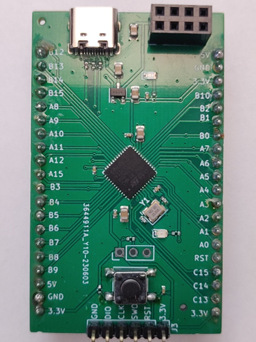
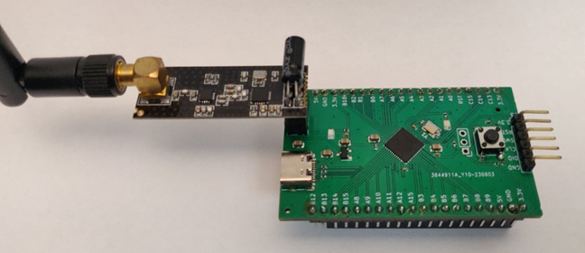
I always love to design simple breakout boards for the controller I like to work with, and the bring up the board with vendor provided tools and take off from there. This is one of many boards I have developed. When I designed this board, I picked STM32F411CEU based on the availability and cost vs feature and a trial run with the board house. I decided to add nRF24 module pinout to a connector and make this board able to equip with wireless solution. Also added in a USB-C connector for future projects.
The nRF24 module
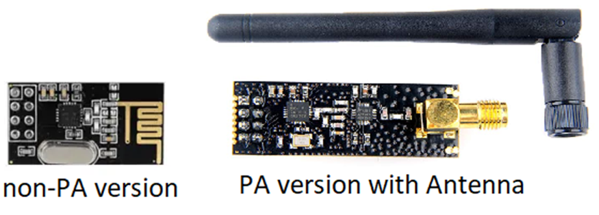
I used the PA (Power Amplifier) version of the module. Because who dosen’t like the long range? Well, I have both the non-PA version and the PA version. For development I used the non-PA version and switched to PA version for range testing.
Project Configuration
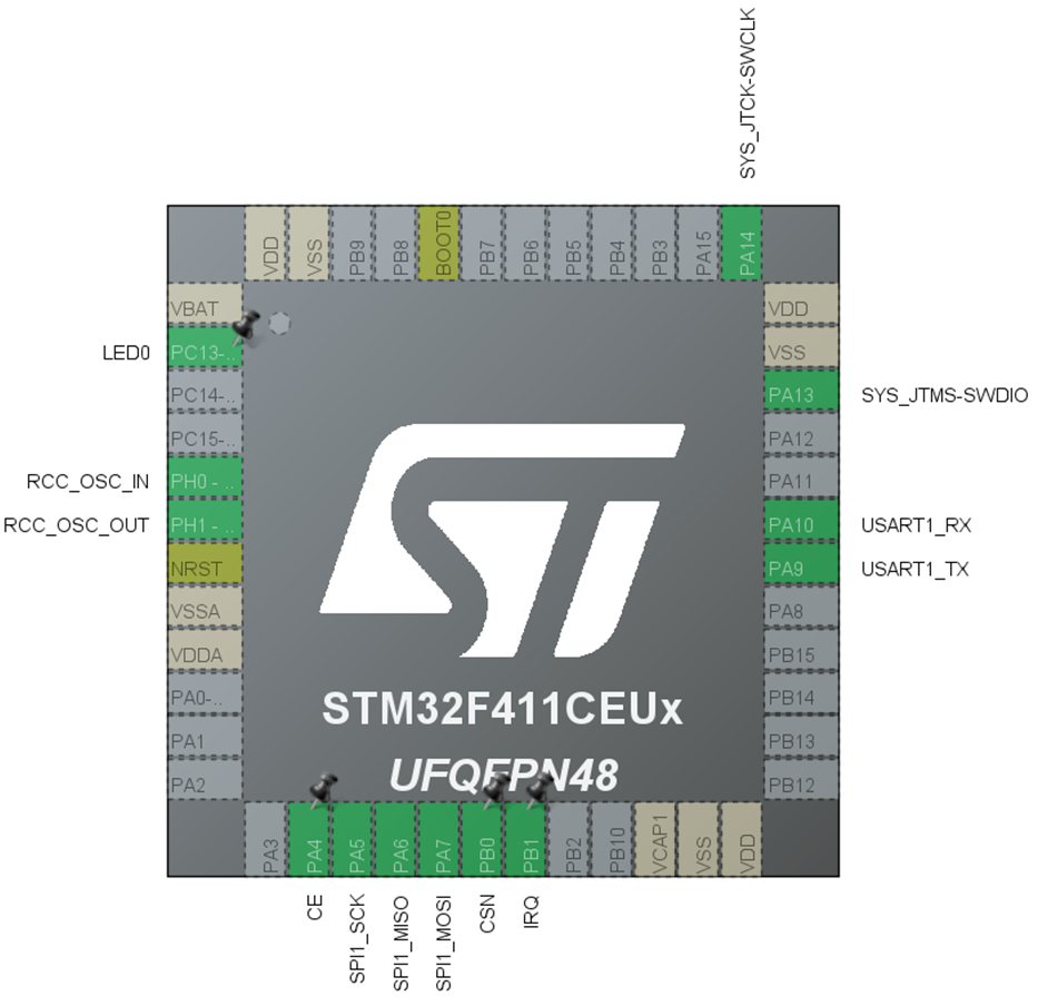
Since I am using the STM32 cube IDE for a quick project layout, here are the list of peripherals that are enabled for this project:
- PC13 – LED0: For heartbeat
- PA9, PA18 – UART1: For input output interface
- PA5, PA6, PA7, PB0, PA4, PB1: For SPI1 <-> nRF24 interface
- Timer 3: For microsecond delay
The code
You can download the source code for this project (and the build files) from my GitHub repository https://github.com/singularengineer/STM32F4_nRF24/tree/master/STM32F411_nRF24
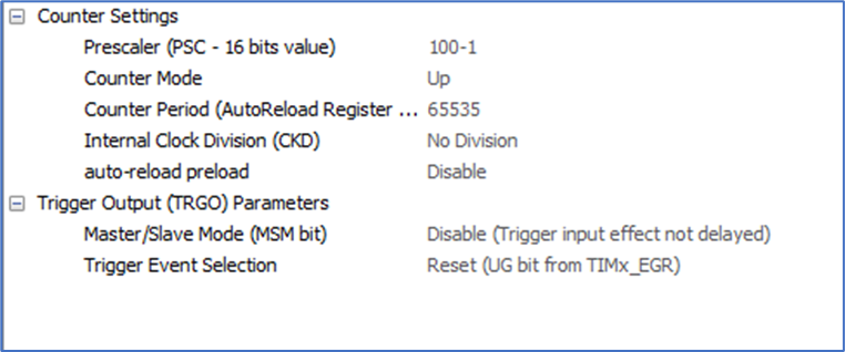
I wrote nRF24 drivers to do very simple initialization and get on the air. It does not use interrupts yet. There are a lot more features this tiny module can do and those features will be enabled in the future as my projects require them. But for now, I just needed something to get on the air. Since the SysTick cannot do microsecond delay in this project, I resorted to using of the timer, ‘Timer 3’ to do the microsecond delay. Here is how the microsecond delay timer code looks like
//To get microsecond delays for the nRF24 module
void Delay_us(uint16_t us)
{
	__HAL_TIM_SET_COUNTER(&htim3,0);
	while (__HAL_TIM_GET_COUNTER(&htim3) < us);
}
The system clock is 100MHz and the timer prescaler is set to 100. That gives us about 1MHz timer counting speed and the counter is count up mode with the counter period set to the maximum value 65535.
I’ll paste the code for initialization and rest of the code is pretty self-explanatory
/* Infinite loop */
/* USER CODE BEGIN WHILE */
HAL_UART_Receive_IT(&huart1, &rxBuf, 1);
HAL_TIM_Base_Start(&htim3);
nRF24Def hNRF;
hNRF.spi = &hspi1;
hNRF.CE_Port = CE_GPIO_Port;
hNRF.CEn_Pin = CE_Pin;
hNRF.CSn_Port = CSN_GPIO_Port;
hNRF.CSn_Pin = CSN_Pin;
hNRF.payloadsize = PAYLOAD_SIZE;
char RX_Buffer[PAYLOAD_SIZE] = {0};
NRF_Init(&hNRF);
NRF_Config("link1", 120, PAYLOAD_SIZE); //PipeName, Channel, Payload Size
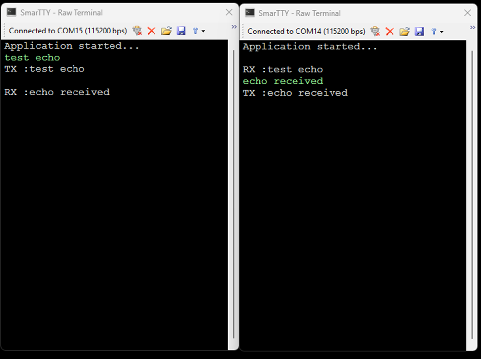
printf("Application started...\r\n");
while (1)
{
NRF_RX_Mode();
if(NRF_Data_Available())
{
NRF_ReadData(RX_Buffer);
printf("\r\nRX :%s \r\n",RX_Buffer);
memset(RX_Buffer, 0x00, 32);
}
if(TX_DataRdy)
{
NRF_Transmit((char *)RxData);
NRF_TX_Mode();
printf("TX :%s \r\n",RxData);
TX_DataRdy = false;
memset(RxData, 0x00, 32);
}
HAL_GPIO_TogglePin(LED0_GPIO_Port, LED0_Pin);
HAL_Delay(10);
/* USER CODE END WHILE */
/* USER CODE BEGIN 3 */
}
/* USER CODE END 3 */
}
Since I am using interrupt on the UART line to capture the incoming packets, here is a how the STM32’s UART interrupt is used
uint8_t RxData[32] = {0x00};
uint8_t rxcount = 0, rxBuf = {0x00};

void HAL_UART_RxCpltCallback(UART_HandleTypeDef *huart)
{
	  if ((rxBuf == '\n') || (rxcount >= 32)) //keep filling the RxData buffer until carriage return
	  {
		  TX_DataRdy = true; //Let the main loop know data is ready for transmit
		  rxcount = 0;
	  }
	  else
	  {
		  RxData[rxcount++] = rxBuf;
	  }
	  HAL_UART_Receive_IT(&huart1, &rxBuf, 1);
}
When the receive buffer (rxBuf) is filled or a carriage return is received, the TX_DataRdy flag will be set to 1. The while loop in the main function will then print the contents of the rxBuf and clear the buffer for the next set of incoming data.