Peripheral Pin Select or PPS use to be a feature available only in 16 bit and 32 bit PICs, but now its available in some 8bit.
Peripheral Pin Select is like having some blank pins that can be assigned as a peripheral pin like UART, PWM, external timer clock and so on of the given choices from the datasheet.
Documents to read
- DS70190 : [Section 30. I/O Ports with Peripheral Pin Select (PPS)] http://ww1.microchip.com/downloads/en/DeviceDoc/70190E.pdf
- C:\Program Files (x86)\Microchip\xc16\(compiler version)\docs\periph_libs
- Device datasheet of the part being used
Example PPS
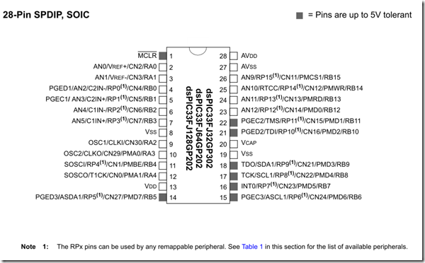
I am using the part dsPIC33FJ128GP202 (28pin package). If I look at the pin diagram, I got 16 Reprogrammable Pins (RP0 – RP15). That’s a lot! Some of them are 5V tolerant which is very important if you are going to hook up a sensor that is giving a 5V signal output.
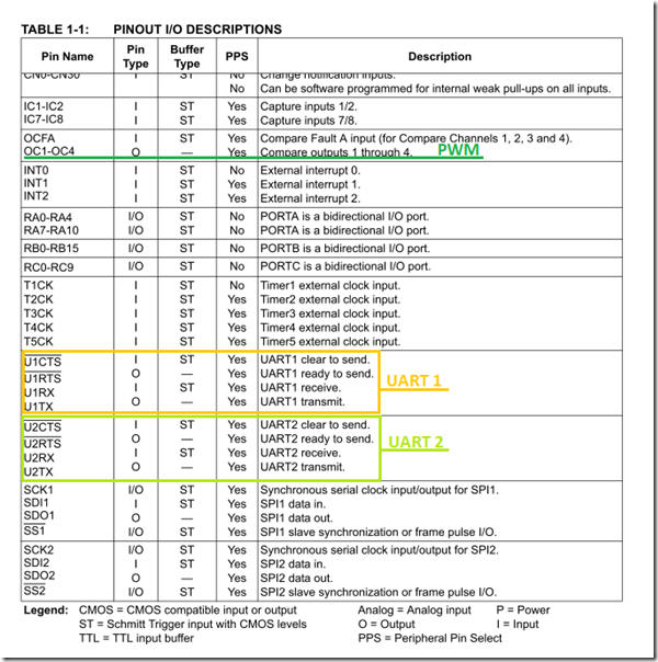
| Note: Pin out I/O Descriptions table (Table 1-1) gives the list of peripheral pin names and PPS functionality. |
Table 1-1 (pin out I/O descriptions) of dsPIC33FJ128GP202
The pins marked here are not listed in the pin diagram. So PPS feature can be used to assign peripheral pin functions.
PPS Sample Code
Steps to use PPS functionality with macro’s
- include pps.h
- unlock pins with “ PPSUnLock “ macro
- PPSInput or PPSOutput function to assign pin (check below for more details)
- Lock pins with “ PPSLock “
If the pin is assigned as an input pin use PPSInput() function, say RX pin of UART assigned to RP7 (pin 16 according to the pin diagram give above). Then the code will look like
PPSInput(IN_FN_PPS_U1RX, IN_PIN_PPS_RP7);
If the pin is assigned as an output pin use PPSOutput() function, say PWM 1 assigned to RP9 (Pin 18 according to the pin diagram given above), then the code will look like
PPSOutput(OUT_FN_PPS_OC1,OUT_PIN_PPS_RP9);
Given below is the sample to properly assign pins with unlock and lock macro’s.
/*
 * File:   dsPICtest.c
 * Author: Singular Engineer
 *
 * Created on January 9, 2015
 */
#define FCY 40000000ULL //Fcy = (Fosc/2); Fosc = 80MHz

#define _ISR_PSV __attribute__((__interrupt__, __auto_psv__))

#include <xc.h>
#include "config.h"
#include <libpic30.h>
#include <pps.h>
#include <outcompare.h> //for PWM
#include <uart.h>

unsigned int i = 0;

void SetupClock(void);

int main(int argc, char** argv)
{

    SetupClock();
    TRISBbits.TRISB0 = 0; //RB0 as output
    LATBbits.LATB0 = 1;   //Turn on the led/RB0

    //---------- Assigning PPS function------------------
    PPSUnLock;

    PPSOutput(OUT_FN_PPS_OC1,OUT_PIN_PPS_RP9);
    PPSInput(IN_FN_PPS_U1RX, IN_PIN_PPS_RP7);

    PPSLock;
   //-----------------------------------------------------
    while(1)
    {

    }
    return 0;
}

void SetupClock()
{
    //Setting N1 to 4 (N1 = n+2); n = N1-2
    CLKDIVbits.PLLPRE0 = 0;
    CLKDIVbits.PLLPRE1 = 1;
    CLKDIVbits.PLLPRE2 = 0;
    CLKDIVbits.PLLPRE3 = 0;
    CLKDIVbits.PLLPRE4 = 0;

    //Setting M to 32 (M = m+2); m = M-2
    PLLFBDbits.PLLDIV0 = 0;
    PLLFBDbits.PLLDIV1 = 1;
    PLLFBDbits.PLLDIV2 = 1;
    PLLFBDbits.PLLDIV3 = 1;
    PLLFBDbits.PLLDIV4 = 1;
    PLLFBDbits.PLLDIV5 = 0;
    PLLFBDbits.PLLDIV6 = 0;
    PLLFBDbits.PLLDIV7 = 0;
    PLLFBDbits.PLLDIV8 = 0;

    //Setting N2 to 2
    CLKDIVbits.PLLPOST0 = 0;
    CLKDIVbits.PLLPOST1 = 0;
}

