UART in 16bit controllers (dsPIC and PIC24) has a FIFO buffer for their receive and transmit buffers. In 8 bit variants the buffer size is 1 byte. For the PIC I’m using (dsPIC33FJ128GP202) it is 4 bytes and may change with different parts (please read the data sheet for RX and TX buffer size). The peripheral library will take care of the buffer for the most part but not always. So just be careful.
In this post I am giving the code snippet without using the DMA feature. Next post I’ll make one with the DMA feature.
`
Documents to read
- DS70000582E : http://ww1.microchip.com/downloads/en/DeviceDoc/70000582e.pdf
- C:\Program Files (x86)\Microchip\xc16\(compiler version)\docs\periph_libs
- Device datasheet of the part being used
UART Setup
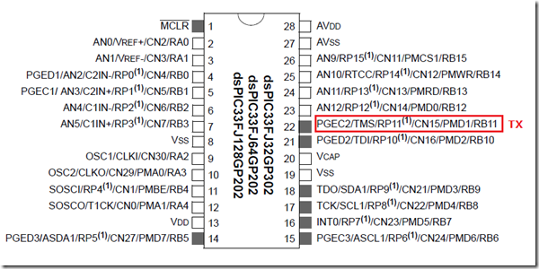
- I am using dsPIC33FJ128GP202 (28 pin SOIC package). Given below is the image that shows which pin I’m setting in for the TX.
I’m using pin 22 (RB11) as UART TX pin.
Steps to setup UART
- Set the TRIS bits
- Set the PPS for the RP pin
- Setup UART settings
| Note: UART has TX FIFO buffer whose size can be found by reading the datasheet. If UART prints only up to maximum FIFO buffer length, then it means TX buffer is full. Using putsUSARTx() function will take care of TX buffer while printing. For manually printing each character, TX buffer has to be handled properly (check the RX code). |
UART Transmit Code
For the most part the comments tell what the settings do. Also the document DS70000582E ( http://ww1.microchip.com/downloads/en/DeviceDoc/70000582e.pdf) will help with a few code snippets too.
In the UART settings you got UART_BRGH_SIXTEEN. Another option is UART_BRGH_FOUR. The way this setting works is by deciding number of clock bits to sample per data bit. This is kind of new compared to the 8bit variants.
UxBRG calculation
The above calculation is when defined as a macro, its easy to edit when the baud rate needs to be changed (snapshot below).
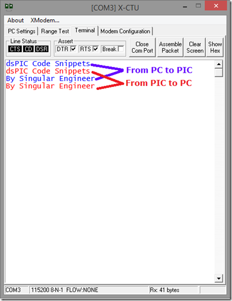
The following code will print “Singular Engineer” every one second approximately.
/*
 * File:   dsPICtest.c
 * Author: Singular Engineer
 *
 * Created on June 28, 2015
 */
#define FCY 40000000ULL //Fcy = (Fosc/2); Fosc = 80MHz

#include <xc.h>
#include "config.h"
#include <libpic30.h>
#include <pps.h>
#include <uart.h>

#define BAUDRATE 115200
#define BRGVAL ((FCY/BAUDRATE)/16)-1

void SetupClock(void);
void SetupIOPins(void);
void InitUART1(void);
void Delay1Second(void);


char *TXData = "Singular Engineer \r";
int i = 0;

int main()
{

    SetupClock();
    SetupIOPins();
    InitUART1();


    while(1)
    {
        putsUART1((unsigned int *)TXData);

        Delay1Second();

    }
}

void InitUART1()
{
    unsigned int UartMode = 0;
    unsigned int UartCtrl = 0;

    UartMode =  UART_EN &       //Enable UART
            UART_IDLE_CON &     //Continue working when Idle
            UART_IrDA_DISABLE & //Not using IrDA
            UART_MODE_SIMPLEX & //Not using Flow control
            UART_UEN_00 &       //Not using CTS/RTS pins by not setting it up
            UART_DIS_WAKE &     //Disable wakeup option
            UART_DIS_LOOPBACK & //Not using in loopback mode
            UART_DIS_ABAUD &    //Disable ABAUD
            UART_NO_PAR_8BIT &  //8bit data with none for parity
            UART_BRGH_SIXTEEN & //Clock pulse per bit
            UART_1STOPBIT;      // 1 stop bit

    UartCtrl = UART_TX_ENABLE &     //Enable UART transmit
            UART_IrDA_POL_INV_ZERO; //VERY IMPORTANT - sets the pin's idle state

    OpenUART1(UartMode,UartCtrl, BRGVAL);
}

void SetupIOPins()
{
    //--------------- Pin Assignment -----------------

    TRISBbits.TRISB11 = 0; //Pin 22 as output pin for UART TX

    PPSUnLock;

    PPSOutput(OUT_FN_PPS_U1TX, OUT_PIN_PPS_RP11);

    PPSLock;

    //-------------------------------------------------
}

void Delay1Second()
{
    for(i=0;i<100;i++)
    {
        __delay_ms(10);
    }
}

void SetupClock()
{
    //Setting N1 to 4 (N1 = n+2); n = N1-2
    CLKDIVbits.PLLPRE0 = 0;
    CLKDIVbits.PLLPRE1 = 1;
    CLKDIVbits.PLLPRE2 = 0;
    CLKDIVbits.PLLPRE3 = 0;
    CLKDIVbits.PLLPRE4 = 0;

    //Setting M to 32 (M = m+2); m = M-2
    PLLFBDbits.PLLDIV0 = 0;
    PLLFBDbits.PLLDIV1 = 1;
    PLLFBDbits.PLLDIV2 = 1;
    PLLFBDbits.PLLDIV3 = 1;
    PLLFBDbits.PLLDIV4 = 1;
    PLLFBDbits.PLLDIV5 = 0;
    PLLFBDbits.PLLDIV6 = 0;
    PLLFBDbits.PLLDIV7 = 0;
    PLLFBDbits.PLLDIV8 = 0;

    //Setting N2 to 2
    CLKDIVbits.PLLPOST0 = 0;
    CLKDIVbits.PLLPOST1 = 0;

}
Output
UART Receive code
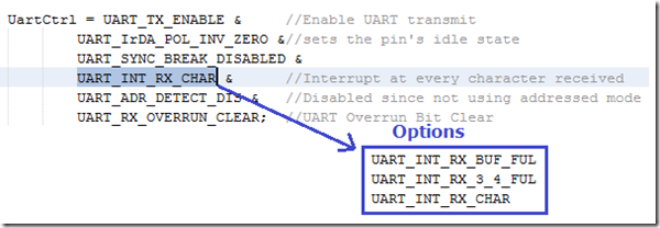
Similar to UART transmitter buffer, the UART receiver buffer is also 4 bytes deep FIFO buffer. So when you setup the interrupt, you got to keep in mind how you set the interrupt to be triggered.
If the FIFO buffer is 4 bytes deep, then an interrupt will happen very 4th byte notifying that the RX buffer is full if UART_INT_RX_BUF_FUL option is selected. And so on. Here for this example I have made UART_INT_RX_CHAR which will trigger an interrupt for every character. If the received character contains a return character ( 0x0D in hex), then it will print everything or if it hits the max buffer size I set.
/*
 * File:   dsPICtest.c
 * Author: Singular Engineer
 *
 * Created on June 28, 2015
 */
#define FCY 40000000ULL //Fcy = (Fosc/2); Fosc = 80MHz

#include <xc.h>
#include <string.h>
#include "config.h"
#include <libpic30.h>
#include <pps.h>
#include <uart.h>

#define BAUDRATE 115200
#define BRGVAL ((FCY/BAUDRATE)/16)-1

#define _ISR_AUTO_PSV __attribute__((__interrupt__, __auto_psv__))

void SetupClock(void);
void SetupIOPins(void);
void InitUART1(void);

char *TXData = "Singular Engineer \r";
unsigned int RXData[32]; //To store Received data
volatile unsigned int RXCnt = 0;
volatile int i = 0;

int main()
{

    SetupClock();
    SetupIOPins();
    InitUART1();


    while(1)
    {

    }
}

void InitUART1()
{
    unsigned int UartMode = 0;
    unsigned int UartCtrl = 0;

    UartMode =  UART_EN &       //Enable UART
            UART_IDLE_CON &     //Continue working when Idle
            UART_IrDA_DISABLE & //Not using IrDA
            UART_MODE_SIMPLEX & //Not using Flow control
            UART_UEN_00 &       //Not using CTS/RTS pins by not setting it up
            UART_DIS_WAKE &     //Disable wakeup option
            UART_DIS_LOOPBACK & //Not using in loopback mode
            UART_DIS_ABAUD &    //Disable ABAUD
            UART_NO_PAR_8BIT &  //8bit data with none for parity
            UART_BRGH_SIXTEEN & //Clock pulse per bit
            UART_UXRX_IDLE_ONE& // UART Idle state is 1
            UART_1STOPBIT;      // 1 stop bit

    UartCtrl = UART_TX_ENABLE &     //Enable UART transmit
            UART_IrDA_POL_INV_ZERO &//sets the pin's idle state
            UART_SYNC_BREAK_DISABLED &
            UART_INT_RX_CHAR &      //Interrupt at every character received
            UART_ADR_DETECT_DIS &  //Disabled since not using addressed mode
            UART_RX_OVERRUN_CLEAR;  //UART Overrun Bit Clear

    ConfigIntUART1( UART_RX_INT_EN & //Enable RX Interrupt
            UART_RX_INT_PR2 &        //Set priority level
            UART_TX_INT_DIS &        //Disable TX Interrupt
            UART_TX_INT_PR0);        //Priority as none

    IFS0bits.U1RXIF = 0;

    OpenUART1(UartMode,UartCtrl, BRGVAL);
}

void SetupIOPins()
{
    //--------------- Pin Assignment -----------------

    TRISBbits.TRISB11 = 0; //Pin 22 as output pin for UART TX
    TRISBbits.TRISB10 = 1; //Pin 21 as input pin for UART RX

    PPSUnLock;

    PPSOutput(OUT_FN_PPS_U1TX, OUT_PIN_PPS_RP11);
    PPSInput(IN_FN_PPS_U1RX, IN_PIN_PPS_RP10);

    PPSLock;

    //-------------------------------------------------
}

void SetupClock()
{
    //Setting N1 to 4 (N1 = n+2); n = N1-2
    CLKDIVbits.PLLPRE0 = 0;
    CLKDIVbits.PLLPRE1 = 1;
    CLKDIVbits.PLLPRE2 = 0;
    CLKDIVbits.PLLPRE3 = 0;
    CLKDIVbits.PLLPRE4 = 0;

    //Setting M to 32 (M = m+2); m = M-2
    PLLFBDbits.PLLDIV0 = 0;
    PLLFBDbits.PLLDIV1 = 1;
    PLLFBDbits.PLLDIV2 = 1;
    PLLFBDbits.PLLDIV3 = 1;
    PLLFBDbits.PLLDIV4 = 1;
    PLLFBDbits.PLLDIV5 = 0;
    PLLFBDbits.PLLDIV6 = 0;
    PLLFBDbits.PLLDIV7 = 0;
    PLLFBDbits.PLLDIV8 = 0;

    //Setting N2 to 2
    CLKDIVbits.PLLPOST0 = 0;
    CLKDIVbits.PLLPOST1 = 0;

}

void _ISR_AUTO_PSV _U1RXInterrupt()
{
    while(DataRdyUART1())
    {
        RXData[RXCnt] = ReadUART1();
        RXCnt++;
        if((RXCnt > 31) || (RXData[RXCnt-1] == 0x0D))
        {
            for(i=0; i < RXCnt; i++)
            {
                while(BusyUART1()); // Wait till TX Buffer has space
                putcUART1(RXData[i]);
            }
            memset(RXData,0x00,32);
            RXCnt = 0;
        }

    }

    IFS0bits.U1RXIF = 0; //Reset RX Interrupt flag
}
Output


