This will be the first of my PIC series. MPLAB X is Microchip’s new (relatively) IDE and XC8 is the new (remember HI-TECH C compiler) C compiler for the 8 bit controllers. Unlike previous Microchip C Compiler (known as MCC18 – for 8 bit) which allowed only PIC18 series, now they cover from PIC10 up to PIC18. Then you move on to XC16 for 16 bit and XC32 for 32bit controllers.
I wanted to start this article by starting a new project and go on, but Microchip has already done a nice job. Given below are the links that you should visit before further reading.
Link for IDE and Compiler : http://www.microchip.com/pagehandler/en_us/devtools/mplabxc/
Link for Installation instructions : http://microchip.wikidot.com/
Problems, “Not working” a.k.a FAQ type questions : http://www.microchip.com/forums/
Yeah, the last link is for some problems you might be facing. I have taken a long time in drafting this whole series and I want to put my time writing it down. So use this as a guide/tutorial.
Before we start, some
Ground rules
1) No bread board – bread board for microcontrollers is a fiasco. If you were having success till now, you are at the mercy of your luck.
2) Read Datasheet – If you did not read the data sheet, then don’t call yourself someone who has used microcontrollers.
Assumptions
1) You know basic electronics (ohm’s law, transistors, etc..)
2) You know logic gates and digital circuits.
3) You know some C, the programming language (yes, we will be doing a lot of C and of course pointers)
Also please download this pdf titled “Microchip XC 8 Compiler User’s Guide” (http://ww1.microchip.com/downloads/en/DeviceDoc/52053B.pdf). As the title say’s, that’s your compiler guide.
| Please leave feedback in the comments section, so that I can improve the quality |
I am using PIC18F4550 and PIC18F46K22, 40 Pin DIP/PDIP package. Codes should be a lot similar. If there is any difference, I’ll let you know.
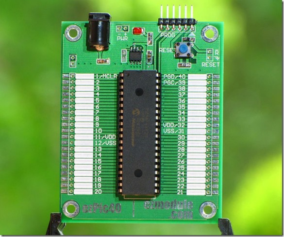
The hardware/prototyping board I’m using is from EZModule.com (http://www.ezmodule.com/). The site has many more goodies for an electronics hobbyist. Here is the picture of the board I’m using (makes your life a lot easier).
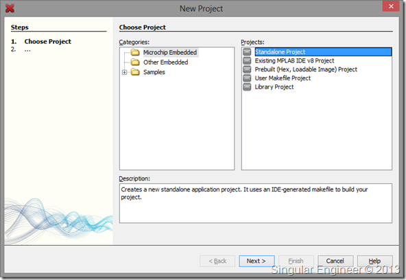
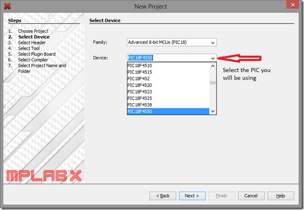
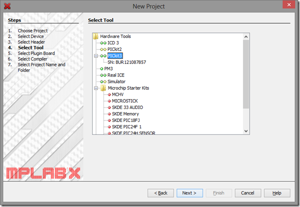
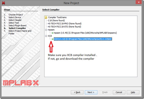
Assuming you have installed the latest version of MPLABX and XC8 compiler, you can start a new project by following the screenshots. Here I am making one for PIC18F4550. It’s the same for all controllers
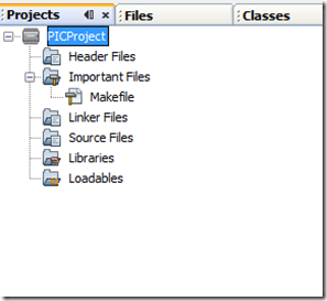
Now we have successfully created a project and this is how the project tab will look like. Its plain and no files inside. Which means we will be adding files to make it work.
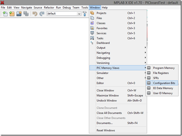
Next step is to create configuration bits. If you don’t setup the configuration bits or if it set wrong, then the microcontroller will not execute anything. Setting the configuration bits wrong or forgetting to set the bits is the first and foremost mistake everyone makes. To view the configuration bits follow the screenshots (Pictures make my life a lot easier)
At the bottom of the screen you will see the configuration bits page.
Setting Configuration Bits
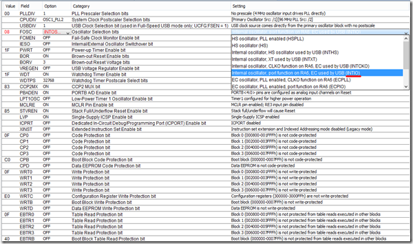
Set Clock (Internal Oscillator)
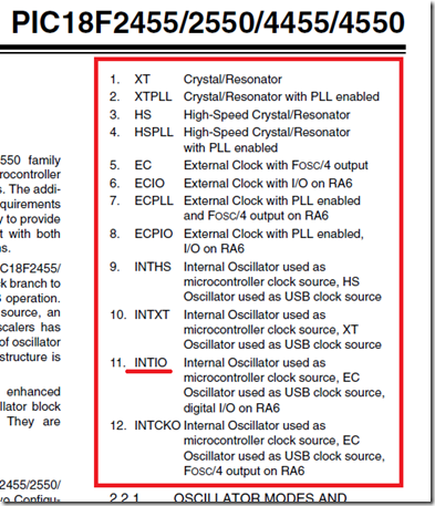
Clock is the heartbeat of the microcontroller. I am setting up the Internal Oscillator as the main clock which means I won’t be connecting any external crystal oscillator or resonators to the controller. The PIC will use its internal components to create its own clock. The internal Oscillator can go upto 8MHz (by default the internal oscillator is 1MHz – read the datasheet). Here is a small screenshot of what clock options you have according to the datasheet
To set the bits you have to flip through the options like the screenshot given below
Now you know how to set a configuration bit, we shall look into the other bits for basic setup.
|
Field |
Option |
Comment |
| FOSC | INTIO – Internal Osc HS/XT – External Osc |
usually HS, but read the datasheet before you set it |
| WDT | OFF | Turn off the watchdog timmer. I’ll cover a chapter on it in the later part of the series. |
| BOR | OFF | Brown out voltage – read datasheet |
| PBADEN | OFF | Will set all the PortB pints to Digital I/O |
| LVP | OFF | Disable low voltage programming – read datasheet |
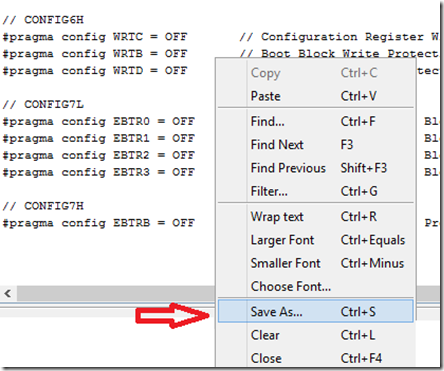
After setting the Configuration bits, you need to save the file. Follow the screenshots
Select all and the save it as “config.h”
Final Setup
We need 2 files for basic operation
1) main.c – our source file
2) config.h – we just saved one
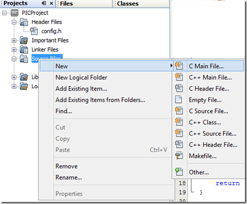
To add a new main.c do the following
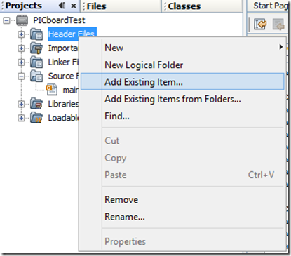
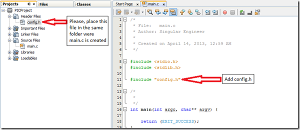
To add config.h (we have already created it – the configuration bits)
Build it now. Build should be successful.
The next tutorial which is the IOPorts
HI,
Your tutorial are very helpful, I was coding your examples using a PIC18F46K22, and those work perfect. Now a need some help I was trying to implement your examples using a PIC18F47J53, because I am trying to understand better a pic18 with USB options, and I fail I followed all the possible configuration words on the datasheet but even that didn’t help.
I was able to compiled an example code and transferred to the PIC without problem but for some reason the pic18f47j53 is no even blinking an LED? I cannot find the problem.
Please could you help to setup a simple blinking LED for the PIC18f47j53 maybe I am doing it wrong on the configuration words, or somewhere else, I don’t know?
Regards.
I don’t have the part 18f47j53. But I can give you some steps that you can follow to fix your configuration.
————————————- Internal Oscillator Config bits (just the clock settings)———————————
#pragma config PLLSEL = PLL3X
#pragma config CFGPLLEN = OFF
#pragma config CPUDIV = NOCLKDIV
#pragma config LS48MHZ = SYS48X8
//In your main program add this function – this should kick it to 48MHz for USB
void SetupClock()
{
OSCCONbits.IRCF0 = 1;
OSCCONbits.IRCF1 = 1;
OSCCONbits.IRCF2 = 1;
OSCTUNEbits.SPLLMULT = 1;
OSCCON2bits.PLLEN = 1;
}
Create a separate application and try setting up UART working instead of blinking an LED and then work on USB. Until you get the clock working perfect you can’t take a step. You can share the code over here if you don’t mind. Also I am working on a USB post after seeing multiple questions as request though email and here. Microchip has already given really good application templates when you install their library.
Good luck and keep posted.
Thanks for the reply, I was trying your changes without luck, I was trying another thing but results at all. just wondering could you provide an email to send you files or the code entirely. I will appreciate it.
BTW, is there a special reason to start with USB and serial instead of the regular I/Os to see the output?
Don’t forget to provide me your email please.
Thanks in advance.
Hi! Excellent tutorial!!!!
I’ve got a question though: Should I include the specific PIC header? (#include , for instance)
Thanks!
When you create a project you specify what PIC it is. So only xc.h is required.
The language is very rude to beginner. ” If you were having success till now, you are at the mercy of your luck.” or “don’t call yourself someone who has used microcontrollers” Find it very abusing on beginners
First of all hats off for you that you read from the beginning. I see it just as a warning than being rude or abusive. The tone is strong and I agree, but if you look at all the comments, they are basically questions from datasheet. So I would ask the readers to see it as a warning.
We need more explanaton about input and output for the programs .. and how to implement these in the program…
Damn, THANK YOU! I’ve been using PIC CCS until now, but I’ve decided to change to a free alternative. I was having some trouble with the CONFIG bits since I started to try to blink a LED. Thanks to the Wizard window, it’s working now. Thanks!
@Gutierrez
Glad it helped you!
Muito bom tutorial, simples e objetivo.
thanks for your great tutorial
I have a problem that the output voltage of my micro pic18f4550 is around 2.8 volt instead of 5v for 1 logic
does someone know the reason and the solution??
I would suggest you to try microchip forums. Any question answered there will benefit a lot of people.
@singularengineer
i will …thanks a lot
Very good intro. Again, good job.
Ah, sry, one remark: don’t agree with the comment on breadboards. It worked well for me all the time, never used any socket board. Actually, I tried one board for fun. Breadboards work for fast testing, you can have one preset, just throw the micro controller in. I do agree that they require care, because electrical contacts are not safe.
@omran
Hello Omran
I don’t know did you solve your problem with 2.8V on digital output but I had similar problem with my PIC18F2455. It turned out that MPLABX set config bit for oscillator to EC by default and of course I was counting on internal oscillator. When I realised my mistake I tried setting Internal osc but code didn’t assemble with settings in IDE. I had to “Generate Source Code to Output” and copy paste it to config.inc and of course include it in main program which I saw here.
Thanks singularengineer!
Other posibility might be that you were using pin that is analog by default (some RB pins) and didn’t set them to digital in code.
Hope this helps you or somebody else with the same problem!
Thank You!
Hello. I am starting with C language using the PIC18. Thanks for your help.
Hello, I’m trying to generate the bit configuration, but I can not generate the code.
Do you know why this is happening? I’m using pic18f2550