Interrupts! You use them to detect the change in pin status, timers, communication and so on. I’m sure if you reached this post in need of using interrupts (or having trouble with interrupts), then I assume you know what interrupts are and what you are trying to use.
With XC8, using interrupts is programmatically simple, since most of the code layout is given to you by <xc.h>. Now setting up interrupts is as simple as using the keyword “interrupt” before the function which should be called when an interrupt happens. I am not going to cover the difference between C18 and XC8 (XC8 makes your life a lot easier), but I’ll show you how to use interrupts in XC8. This post will have only the input from pin change. The timer interrupt will be covered later in the timer chapter.
I encourage you to read the datasheet in order to understand much better about interrupt registers.
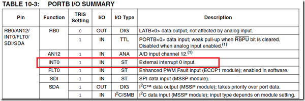
Make sure the IO pin you are going to use for interrupt actually has interrupt feature. Because I have seen people using some random pin out of nowhere and say interrupt is not working. Usually PORTB has most of its pins with interrupt capability. As you know I have been using PIC18F4550 here and according to the datasheet (screenshot below), RB0 is INT0. So now I will be connecting a switch pulled up to VCC. When the switch is pressed, the pin voltage becomes zero. So I will be setting the interrupt to work at the falling edge.
In order to make the pin RB0 to handle interrupt these are the following steps
- Set RB0 as input pin (set the TRIS as 1)
- Enable the interrupt bit for RB0
- Set rising or falling edge interrupt
- clear the interrupt for the pin (just to make sure)
Follow the 4 steps to enable the interrupt and here is the code snippet for RB0
TRISBbits.RB0 = 1; //set RB0 as Input

INTCONbits.INT0E = 1; //enable Interrupt 0 (RB0 as interrupt)
INTCON2bits.INTEDG0 = 0; //cause interrupt at falling edge
INTCONbits.INT0F = 0; //reset interrupt flag
Finally you got to just enable the master switch for interrupt
TRISBbits.RB0 = 1; //set RB0 as Input

INTCONbits.INT0E = 1; //enable Interrupt 0 (RB0 as interrupt)
INTCON2bits.INTEDG0 = 0; //cause interrupt at falling edge
INTCONbits.INT0F = 0; //reset interrupt flag

ei();     // This is like fliping the master switch to enable interrupt
When an interrupt happens, you need a subroutine (fancy word for function) to do something.
Here are is the order you need to handle and interrupt
- Check if the interrupt flag to make sure the IO pin caused the interrupt (or the peripheral you are looking for)
- Do your task
- Reset your interrupt flag
Code snippet for interrupt subroutine
void interrupt low_priority CheckButtonPressed()
{
    //check if the interrupt is caused by the pin RB0
    if(INTCONbits.INT0F == 1)
    {
        LATB4 = ~LATB4;
        INTCONbits.INT0F = 0;
    }

}
So, you have to keyword interrupt and then say it’s a low_priority or high priority
Note: Read the datasheet for proper way of setting the high and low priorities. No matter how how many code snippets are out there, without reading and understanding the datasheet, there is now way you can get outputs as expected.
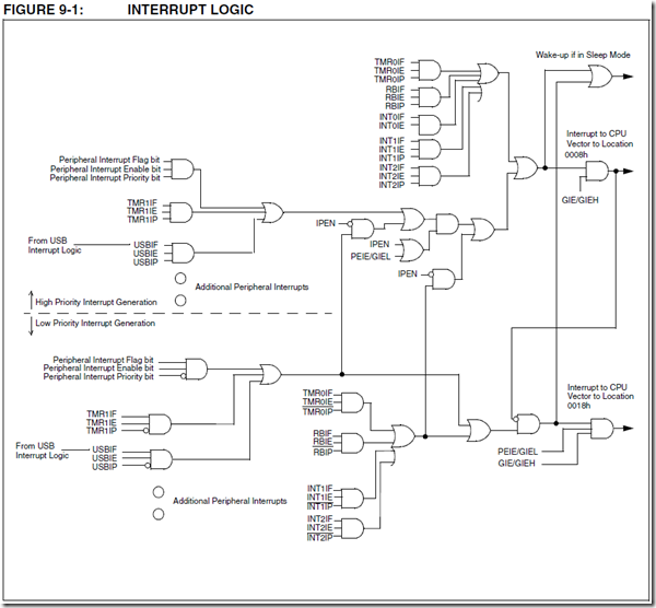
Compare the code snippet and the logic diagram. Will make a lot of sense and you should be able to take from there.
Here is the complete code
#include <xc.h>
#include "config.h"

#define _XTAL_FREQ 8000000 //What ever speed you set your internal(or)external oscillator

int i = 0;
void DelayHalfSecond(void);
void SetupClock(void);

void main(int argc, char** argv) {

    SetupClock();

    TRISBbits.RB4 = 0; //set RB4 as Output
    TRISBbits.RB0 = 1; //set RB0 as Input

    INTCONbits.INT0E = 1; //enable Interrupt 0 (RB0 as interrupt)
    INTCON2bits.INTEDG0 = 0; //cause interrupt at falling edge
    INTCONbits.INT0F = 0; //reset interrupt flag


    ei();     // This is like fliping the master switch to enable interrupt

    while(1) //infinite loop
    {
      //actually we have to put the processor in sleep which i will cover
      //  in later tutorials
    }


}

void DelayHalfSecond()
{
    for(i=0;i<50;i++)
        __delay_ms(10);
}

void SetupClock()
{
    OSCCONbits.IRCF0 = 1;
    OSCCONbits.IRCF1 = 1;
    OSCCONbits.IRCF2 = 1;
}

void interrupt low_priority CheckButtonPressed()
{
    //check if the interrupt is caused by the pin RB0
    if(INTCONbits.INT0F == 1)
    {
        LATB4 = ~LATB4;
        DelayHalfSecond(); //like a debounce
        INTCONbits.INT0F = 0;
    }

}


possible typo:
TRISBbits.RB4 = 0; //set RB4 as input
TRISBbits.RB0 = 1; //set RB0 as output
In this case RB4 is an output, and RB0 is an input.
Yes, unfortunately making a change in the code snippet after a post is very difficult (messes up the formatting). Thanks for making a note (most people just copy paste) 🙂
Hi,
Another confusing thing according to the interrupt picture INT0 is always high priority.
Your code handle it like a low priority.
Btw many thanks for these high quality tutorials. They help a lot to me. Keep up the good work.
All the best,
Tom
Hi I am a PIC beginner.
I’m not testing your code yet but I just curious.
According to your code:
How the compiler know that you intend to call CheckButtonPressed function for the the interrupt?
I don’t see you specify it anywhere.
One theory that I made up is every interrupt call that routine.
And you have to check it by INTCONbits.INT0F bit
but that not make sense since obviously there are high_priority interrupt as well
so at least compiler should allow more than 1 interrupt routine.
Also you named the routine very specific in my opinion not just any interrupt should call the routine.
You see the “interrupt” keyword when I define the function? That “interrupt” keyword tells the compiler that any interrupt happens anywhere, call me (the function CheckButtonPressed).
There are 2 types of interrupt. High and low which is the other keyword being used when defining an ISR function. 8bit controllers do only nested interrupts. Which means when interrupt happens, you need to have an “if” condition to look at which peripheral created the interrupt. In case of 16bit and above they are addressed individually with upto 8 priority levels (compared to high and low in 8bit case).
Hope I explained what you asked for?
@singularengineer
I got it.
Thanks,
so my theory seem to be true.
There are only 2 interrupt vectors high and low priority.
What cause the interrupt should be checked in interrupt routine.
no dedicated vector for each interrupt.
Then I suggest you to rename interrupt routine to clarify your code for some beginner. (like me)
Its name should be more general for any interrupt and move CheckButtonPressed into the comment.
Thanks for the comments. Making a change in the post after its published is a pain since the formatting goes everywhere. But i’m sure some people go through the comments and you have summarized it excellently!
Thank You!
Thanks , I learn in details now , Keep going and cover PIC32 please
I started studying about XC8 compiler according to your guidelines. When I reached the interrupt section I was having a doubt. INT0E and INT0F is not listed in the intellisense menu of INTCONbits. Instead it is having options like GIE, INTE, INTF,PEIE, RBIE, RBIF, T0IE,T0IF, TMR0 and TMR1. Even if the code is compiling successfully it is very difficult to use. I there any solution to solve this problem? I am using MPLABX 2.05 and XC8 1.30.
Don’t rely too much in intellisense. Read the datasheet and follow it.
Hi,
Thanks for the tutorial.
I browsed the microchip forums and found that for interrupt code, they use
#pragma code hvector = 0x08
void hvector(void){
_asm goto hisr _endasm
}
#pragma interrupt hisr
void hisr(void){
//isr goes here
}
I think the above code is written for older compiler. My xc8 cannot understand what is “code”
it gives warning as – Unknown pragma “code” and unknown pragma “interrupt”
also, it throws error at the _asm line.
I read the xc8 manual and your tutorial and declared as told by you. Now it compiles ok.
my question is, if we declare as
void interrupt hgh_isr(void){
//h priority isr goes here
}
will it not be able to use the goto feature here? (I think they used the goto feature at 0x08 since the isr will not fit in the memory allocated to the isr)
if that is the case, in the new xc8, will the compiler see to this problem, or should we do it like the one above?
Thanks.
The compiler will take care of it.
Hi I am a PIC beginner.
Please let know how to use Interrupt when the timer is overflow in MPLAB.x using XC* compiler.
Please also let me know how to use the timer four the same ISR or the Interrupt service routine.
Tanks a lot
Navin Luthria.
India.
I have the same problem, where is the tutorial to solve it? It give warning as a unknown pragma code @Anish
@Adan
Don’t have a clue who’s problem you are talking about.
If you are looking for #pragma for interrupt code, you don’t need that in XC8 compiler. If you are using C18, then you need the keyword pragma to tell it is an interrupt function. This is a XC8 tutorial.
Hello from France,
Thanks for this tuto that goes strait to essential.
Very usefull
there’s a typo when you say to put RB0 as output, it’s input.
Yes. Thanks. Fixed now.
Usually making a change in the code area after it a post is published is quite difficult (at least with the tools i’m using.)
Thanks again.
hi, i am starting pic18f26k80 with xc8 compiler for hcsr04 ultrasonic sensor….
please tell code for above sensor…thanking you
Your tutorials on Timers, interrupts for XC8 are invaluable. I wonder if your going to do something on capture ie pulse counting and period measurements. There is lots on PWM but very little on CCP with !8F series. Some stuff on C18 but little on XC8. Do you have anything helpful at the moment.
Things I have written here are code that I have to write for something else. I haven’t come across a need for CCP yet. But if you find any C18 code for CCP, you should be able to use them for XC8 with little or no change. All the best.
@raja
Hello my friend, I use the pic18f26k80 too but I get not use interrupt function. Can you help me?